
Time to upgrade the old narrowband sensor with wideband. This is partly due to continued challenges getting emissions correct for MOT, partly because its something new to play with, and significantly because I was made aware of a wideband setup with an in-build calibration mode to null out some variables caused by the install.
I'm chasing the holy grail of calibrated emissions using home/garage equipment without a full blown rolling road remap.
I'm chasing the holy grail of calibrated emissions using home/garage equipment without a full blown rolling road remap.
Installation
I don't need a dashboard indicator - so went for the simple sealed unit.
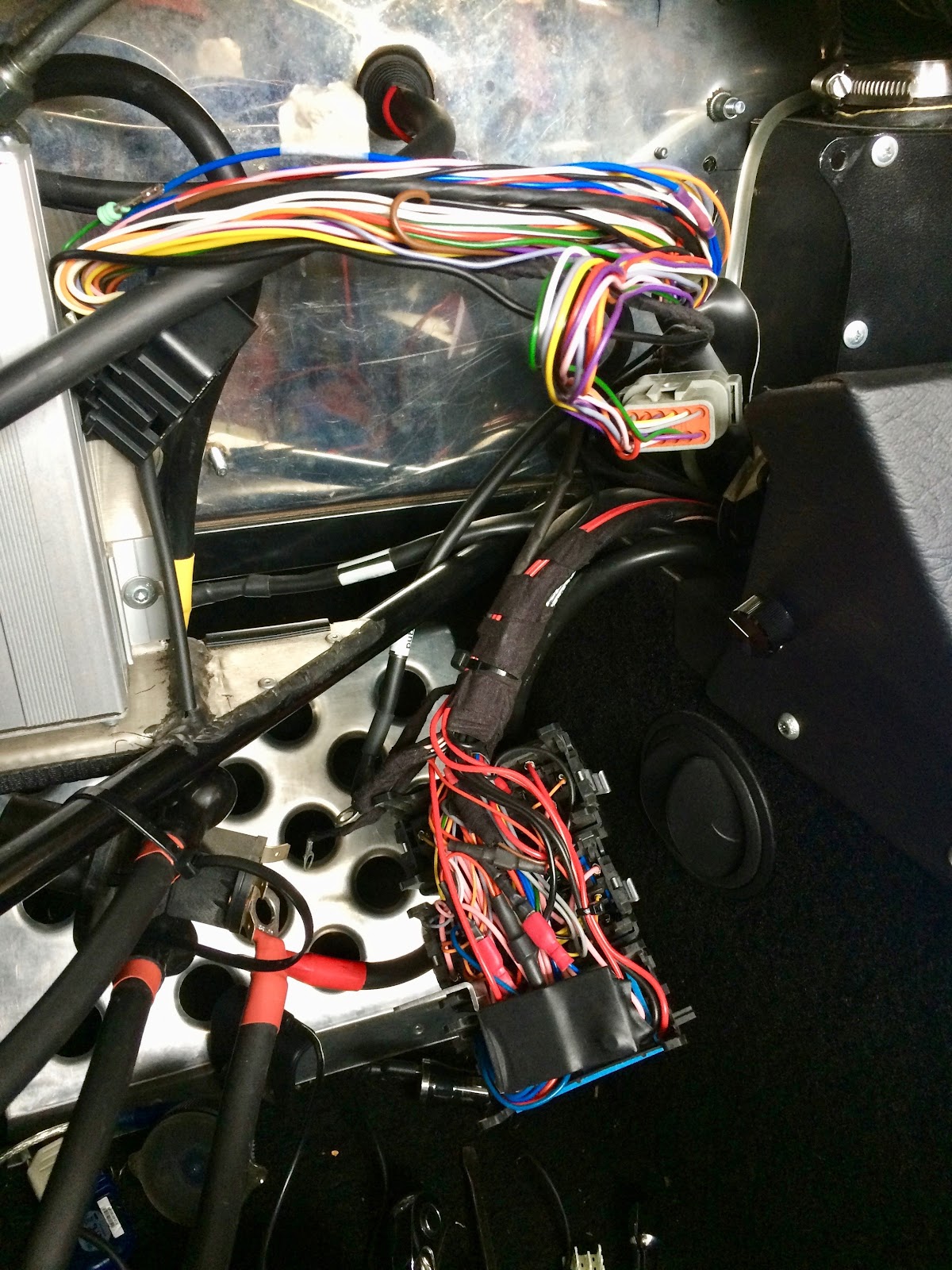
The processing box was installed in the engine bay next to the gearbox - which should be reasonably protected from both the road and away from the hottest parts of the engine bay.

The sensor must not be detached from its cable or plug - due to built in calibration - meaning a hole in the car side panel large enough for the whole sensor to pass through. A small marine clamshell covers the hole, riveted in place for simplicity - if I ever need to replace the sensor its easy enough to drill out the rivets.


Wiring
The unit has simple wiring requirements - 12v, Main and Signal Grounds, optional LED output and a couple of Lambda outputs for wideband and simulated narrowband. Sensor ground and wideband feeding into the Emerald on pins 30 and 34 currently. Best advice from Emerald is use pin 10 as the input - however its working fine on 34 so I'm not changing just yet.

I wired in another circuit for it through the main fusebox to avoid having a trailing inline fuse on the loom, while everything was open I unsheathed and re-bound this part of the loom.
The Spartan2 takes its power from the ECU relay via its own 5 Amp fuse so starts up and shuts down when the ECU does.

Calibration
The interesting part of the Spartan2 is the calibration mode.
This permits correction for linear shifts and angle of the AFR graph, not the shape of the graph, but should factor out differences/voltage drops in installation wiring and even differences in Emerald's voltage measurement.
As soon as the wide-band module starts up it sends 2x known voltages/AFR readings, 5 seconds each, to the ECU.
This permits correction for linear shifts and angle of the AFR graph, not the shape of the graph, but should factor out differences/voltage drops in installation wiring and even differences in Emerald's voltage measurement.
14Point7 supplies a spreadsheet which converts the calibration AFR outputs to two corrected points which can be input to Megasquirt ECU.
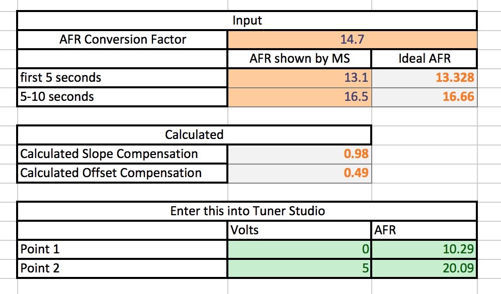
Emerald has a single decimal place on AFR, but shows and allows entry up to 3 places on voltage - so I re-worked the OEM spreadsheet to input voltages and calculate voltages from known AFR values.
Entering the calibration readings in volts, 1.642 and 3.314, in the top green boxes and the desired AFR points the sheet works out the voltages which correspond exactly to those AFR values.
Emerald does not allow selection of every voltage so the error column works out the potential error due to data entry - negligible and well inside the wide-band units accuracy.

.. Just needs copying in to the ECU settings and job's a goodun.
I suspect the wide-band has enough damping built in - so reduced the emerald signal smoothing to 0.

Gotcha - the only issue I found was by the time the ECU had powered up and connected to my laptop the wide-band had already gone through its calibration steps. The resolution was to power everything up with the wide-band fuse out, open the right Emerald Lambda screen then plug in the wide-band fuse, only needs doing once to calibrate.
Minor tweaking to restore the original powermap target AFR, and adjust the closed loop gain to get a stable idle. The idle zone used to have a lower AFR on the 500 revs column - meaning, as the ECU interpolates, its getting mixed messages - I flattened that out to 14.7 to try and give it an easier time of finding a stable tick over.


The only way to prove this is correct is a garage/MOT testing equipment - but it should be getting close & now have the controls to find the right emissions settings and have the ECU reproduce them using active feedback. I'm planning to try with a friendly garage pre MOT (next June) and if that fails a rolling road.
Holy cow, I have no idea what you're on about. I'm wimping out on all this and getting a Q plate so I don't have to worry about MOTs.
ReplyDeleteYup :) good option!
ReplyDeleteThis is certainly a rabbit hole - but quite interesting none the less, especially since the work paid off on the last MOT.
Hey Richard, any chance you could share a link to the calculation spreadsheet? I am struggling with the math side! Surprisingly I cant find any other reference to calculating the voltage values for Emerald so I am stuck, I also have a Spartan 2 but its not yet configured. Thanks!
ReplyDeleteCheck out this page on the 14point7 site - there is a link half way down to their spreadsheet which generates 2x points - you then need to adjust for the 6 or so Emerald uses:
Deletehttps://www.14point7.com/blogs/news/16539352-maximizing-accuracy-between-spartan-2-and-megasquirt?_pos=2&_sid=02e081a8e&_ss=r
I think my brain has stopped for the day, will pick it up the morning. Struggling to convert the sample sheet from 14point7 to voltage like your screenshot, I have re-created most of your sheet in Excel I just cant understand the formula for "volts at 0 AFR" and also the calculated input voltage for each point. Math definitely not my strong point...
DeleteThe Emerald chart on the settings page is buggy too - it makes assumptions about one of the axis. The table input is fine - it just draws the wrong shape graph. If all else fails break out the graph paper and draw on the lines the default 14point7 sheet gives you? Send me you email (I won't publish it here) and I can share my osx/numbers sheet if that helps - it might be a bit cryptic though.
DeleteHi Richard, I finally worked this one out. You might find this obvious but its the bit that got me stuck, I'll put my workings out here in case it helps someone else in the future.
ReplyDeleteA = the voltage seen in the Emerald software for the first 5s, We know that this represents 13.328 AFR. In my case 1.657.
B = the voltage seen in the Emerald software for the second 5s, We know that this represents 16.660 AFR. In my case 3.338.
C = Recorded voltage range, B-A in my case 3.338-1.657, 1.681.
D = AFR range. This is the difference between the first and second known AFR reading, 16.660 - 13.328, 3.332.
E = Volts per AFR. This is C / B, in my case 0.50450.
To calculate Volts at 0 AFR we use: (A-(E*1.328))-(12*E). In my example this would be (1.657-(0.50450*1.328))-(12*0.50450) giving a value of -5.067v.
I realize that sounds a little like the ramblings of a mad man...but at this point in time, in my head, it makes sense. I hope that helps you\someone else in the future.
Thanks,
Dan
TBH - i didn't check your working in detail (and I'm sure you don't need me to)
DeleteThe whole thing does take some to get your head around, I'll agree!
Emerald likes to throw in the curve ball too by only allowing certain voltages selected.
I'm a tables man in excel - row by row & graphs.
Good fun though!