Showing posts with label wiring. Show all posts

Monday, 5 October 2020

Cooling fan manual and backup stat overrides

 A little enhancement on the main engine cooling fan control.

While the ECU fan management is rock solid it is at the mercy of input sensors.

It is straightforward to add a manual switch into the fan relay coil as an override. If my temp sensor ever goes bad again the switch under the dash will let me manually turn on the engine fan.

To make things more interesting I incorporated a tri-colour LED to show on the dash when the fan is on, it sits unobtrusively bottom right of the water temp gauge.

The circuit specifically designed for minimal changes to the main loom - just a piggy back on an existing cable and if my new circuit fails - for any reason - it should not disturb or otherwise upset the existing operation of the ECU to Fan relay circuit.

Off = fan is off

Green = fan on via ECU demand


Red (ish) = fan on via Manual dash switch demand (its actually red + green but the red is more intense)


Blue = fan on via Radiator stat demand

I have a VW Polo radiator with a mounting point for a simple temp sensor which closes a switch, and for me, grounds the cable when it hits a temp limit. This is the automatic backup if the ECU sensor fails again & will light blue on the dash as a warning.


Multiple demand on at the same time light green + the appropriate colour.


Circuit

The circuit itself on a Vero board mounted behind the dash with manual override switch beneath. The board is in one of the drier areas of the car but precautionary hot glue on cable ends and the board conformal coated to give it a chance in the relatively harsh environment.

All wire runs were subsequently given a second layer of insulation/soft fabric wrap too.

Emerald Pin 6

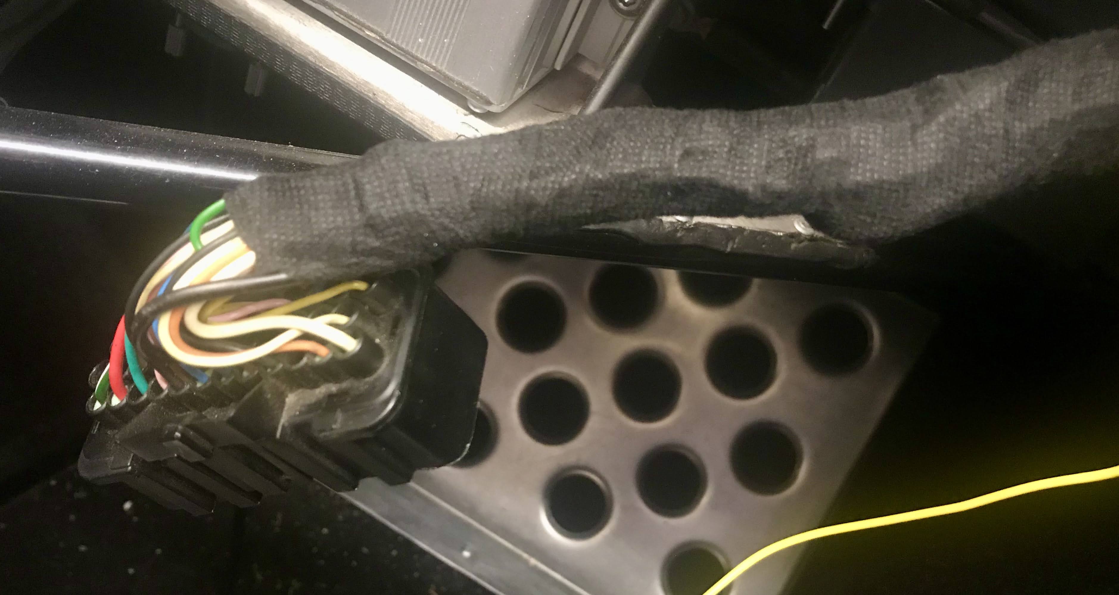
Emerald Confirmed that the ECU will not mind an external sink of pin 6 'Fan Relay control' to ground. The easiest place to tap into it on my car is near the ECU connector - a cable spliced on and suitably insulated.

These are all signal current circuits to the coil of the Fan relay - no significant current passing at any time.  Traced pin 6 to the orange wire - double checked by grounding it does turn on the fan - and spliced in my yellow feeder to the new circuit


Wrapped it all back up

That will do.

Monday, 26 March 2018

LED Headlamps

Finished the wiring for the headlights, whether they are MOT legal or not is yet to be tested.

The LED headlight lamps I chose had a built in quirk that they would not light full beam and dip beam at the same time. My loom tried to illuminate both when on full beam - and for a long while I've just planned the fix.

The LED bulbs have deflectors for dip/main to move the light generation point appropriately for my lenses. LED pictured top using the same connector and a built in fan, high intensity halogen H4 bottom.


Two choices - dive into the fusebox again and adjust the headlight circuit or, what I decided on, a flying loom in the front of the car to cut the dip beam when full beam is on. The circuit is designed to be non-destructive by plugging into the existing loom and will still work with normal H4 bulbs:

Picked up on the same colour scheme as the existing loom with high enough gauge to also support normal bulbs, if the LEDS don't make it through MOT then I can simply revert the bulbs and leave this circuit in place.

My least favourite part of the car, I just can't seem to make it look tidy - the new flying loom plugs into one side of the headlight feed then connects to the headlight leads. The relay mounted to the existing horn attachment point.


Works well enough - the relay on the flying loom simply cuts power to dip when it sees main, no changes required to existing switches or fusebox, the dip pattern seems to work - although not completely visible on these pictures - horizontal top with a kick up to the near side.

Dip, Full beams, lenses themselves look like they need rotating to get a level output.

Next step is run the lights through an alignment test and confirm if I'm legal.
To be continued...

Update - Bigclive.com Youtube channel just did a teardown and explanation of these bulbs, bears our my experience with them not supporting main and dip on at the same time. Very interesting.

Tuesday, 20 February 2018

Testing - volts LED, Power distribution and crank breather

First chance to run the engine in ages.

Three changes to test:

Success 1
LED indicator works fine - showing red or amber when ignition is on, and then flips to green as soon as it sees the voltage climb, that should be easier to read at a glance than the volts clock.

Success 2
Power routing changes are excellent - between .5 and 1volt more showing on the volt meter - I actually see 14.5 volts when charging at ~1,000 revs. Well worth doing to make the shortest cabling runs with fewest connections possible.

This did require a tweak to the idle injection settings, I think the ECU battery voltage compensation was reducing cycle times a little over optimistically. I adjusted idle so the wideband is within its adjustment thresholds and feels like I need some more long distance driving to let the rest of the map settle down.

Success 3
No difference with the breather change - I checked by blocking the hole with my finger - engine isn't bothered either way. Time will tell if this stops my dipstick being pushed out on more spirited runs.

Sunday, 18 February 2018

Earth point re-work

While changing the power distribution; quick tidy on the internal chassis earth point.

Before - too many cables on the one bolt making things untidy and awkward to maintain, every time I removed/re-inserted this bolt it was juggling at arms length in the footwell.

After - simple busbar - much better, tidy and I can remove the battery ground cable without everything else moving around.

Tuesday, 13 February 2018

Power distribution changes - battery fusebox prep

Re-working the power distribution circuit.
There was no massive issue with the original standard setup however - reading through various sites over the years I noticed there was always at least a fusible link somewhere in the setup and on many modern cars a fusebox right on the battery. 

The stock Zero had no such built in weak point - just massive 35mm² cabling, and plenty of it from the positive battery terminal in the engine bay and behind the firewall before any fuse. When everything works, as it has for 4.5 years, its fine, but a failure in any of these cables insulation could be serious.

Power distribution layout changes

The stock Zero cabling is routed: Battery->fusebox binding post->starter->alternator.
The isolation switch is my own addition - helps ensure everything is off when the car isn't actually being driven.

The new arrangement will have physically shorter runs, not via the firewall, not taking the usual alternator->starter route which is significantly longer on a RHD Zero. It also minimises cable joins.

I'm moving my isolation switch to the negative side of the battery at the same time - again safety - less unfused cabling just waiting to find a short.

Downside?

a. If the alternator fuse blows with the engine running, the alternator is likely to cook itself. I'm positing if this fuse goes I've probably got bigger issues to worry about anyway!

b. If the isolator is used with the engine running its also likely to blow the alternator. The switch is only used to disconnect the battery when I'm not driving and/or working on the car. Its an isolator not a kill switch.

Battery mounted fusebox 

The positive battery terminal to be replaced with a fusebox - found on ebay by searching for 'Renault battery terminal' - its perfect for the job, originally used on Renault Scenics so should be up to the task.
   1x CAL 1 Powerfuse for the starter, 
   1x 80A midifuse for the main fusebox (60A pictured)
   1x 80A midifuse for the alternator (60A pictured)

My alternator is 40A output could hit ~50, therefore fusebox should only be drawing ~50A and fuses sized at 80A to run at ~75% of their rating and well under the 16mm² cable rating.

The box required a couple of minor modifications, first picture, the midi line exit holes in the case needed a little adjustment to accept a standard 6mm cable end.

The lid also needed a little of the bottom edge removed to fit around my battery.

Offered up, I think I'm going for this orientation - two cables leaving for the starter and alternator, one the other side toward the fusebox. There's plenty of room under the bonnet at this location.


Update - engine run test, better voltage indicated on the clocks so thumbs up for the wiring change. The significantly shorter runs and fewer joints have given me a good 1/2 a volt perhaps more indicated - I'm now seeing 14.5V on the volt meter instead of the usual 13-13.5.

Update - up-rated 2x midi fuses to 80A for more headroom. Spec on the 40A alternator shows it could hit 52A in normal operation.

Update 2 - I think the extra 1-1.5 volts upset the injection settings - perhaps an over enthusiastic default battery voltage compensation curve in the ECU. I lost slow idle and had to boost the injection values a little so get back in the range where the wideband live adjustments can do their job and not pegging at its set +-15% settings. ECU settings updated to compensate.

Polyswitch bypass

Moving the isolation switch to the negative lines means I need a different approach for a permanent live. My radio and immobiliser flashing LED need a trickle current even if the isolator is turned off, they draw around 10mA total.

Going back to the polyswitch approach, this time a modified blade fuse which can sit in a standard holder. This sits across the isolation switch and will let low currents pass but then open completely if, for example, the ignition is turned on or anything tries to draw more than 100mA. Once the current drops below 50ma it resets itself and everything is back to normal.

All set for final assembly and testing.
(Garage is still to cold to work in for any length of time)


Update - jury is out on the PTC - problem is if I turn on the hazzards (which are live even with ignition off) they trigger/reset the PTC continuously due to drawing the trigger current then immediately turning off, PTC doesn't mind - but the flasher relay will.

Either the PTC goes, or I mod the hazzards switch to have a constant ~50mA load.

Sunday, 4 February 2018

Volts - dashboard LED indicator

Couple of hours spent on a project to enhance battery voltage reading.
The unit I'm installing produces various LED colour combinations to flag over and under voltage, so the same information as the existing dial based volt meter - except - its in a more 'in my face' or 'read out of the corner of my eye'  way.

I know I'm tight on electrical power when pausing in traffic with idle revs and headlights on, i.e. usually right at the end of a long road trip. I usually only remember when I start to lose smooth idle. Hopefully this LED catch my eye and I'll be ready to manage the revs a little.

Simple tap into the existing volt meter loom - just need the +ve and -ve feeds.

The 5mm LED discretely installed next to the volt meter, if you didn't know it was there you'd probably miss it.

The widget is a self contained micro-controller and RGB LED, sold by Gammatronix on Ebay at a delivered price less than I could have achieved with off the shelf parts.

Two modes to show alternator output/charging or static battery levels. I'm interested in the former so cut the yellow line - potentially a pushbutton across that line would allow both modes.

All tests fine on the bench, road tests will have to wait until I re-install the main high current power distribution circuits via a battery top fusebox.

Update - works fine, the LED isn't super bright so could do with a recessed bezel, but indicates when on charge fine.

Saturday, 3 February 2018

Wiring diagrams - power, dashboard and aux panel

Starting to document the wiring with the parts I have, or am in the process of, modifying.

Detail on components used to follow.
Common lines - +ve, ground and illumination omitted for clarity.
Colours directly indicating wiring colouring.

The pictures are large - right click and download for full resolution.


Power distribution

Some adjustments from the stock loom part way through implementation - with a battery mounted fusebox eliminating all unfused cabling. 
- The isolation switch is an FIA type switch, not used for engine cutout (it would blow the alternator if the engine was running) but generally used to isolate the battery when the car is parked or when I'm working on the electrics. 
- The PTC is a Polyswitch to allow trickle current for the radio and immobiliser permanent live even when the isolation switch is open.

Dashboard loom

Mostly stock, with some additions: The secondary 'in my face' direction indicator warning light (to stop me leaving them on), a shift light triggered by the ECU and a secondary volt meter LED warning light.


Aux Panel Loom

This one very heavily modified on the panel and main loom side to include: a map switch, 12v back panel power outlet and radio/amplifier system. The switches are all back lit when side lights are on and telltale brighter illumination when switched on.


The holy grail is a clear fusebox wiring diagram, that one is going to be a little time consuming!

Update - Adding in connector diagrams and Polyswitch bypass on the power distribution.

Tuesday, 25 July 2017

Flick wipe steering wheel switch

Moving the flick wipe switch from its initial position on the aux panel up to the steering wheel. The original position needs me to take my hands from the wheel and the button wasn't the best for finding with gloves on.

The new button - stainless and weatherproof. I made a small bracket from an aluminium offcut.

One 3.2mm hole into the side of the hub - after much discussion on whether that was a good idea - de-burred and sealed with glue to prevent any possibility of chafing. The bracket attaches on the back of an existing steering wheel bolt - so shouldn't affect safety in terms of wheel attachment.

My column is earthed - I found if I actively earth the mounting bracket, blue wire and eyelet, it also earths the top of the column and hub. There must be a conductive bushing inside the top column casting.

An earthed steering hub means the 2x contacts on the slip ring can be used for separate circuits. Horn takes one, my new flick wipe button the other. Both are intermittent and low current, activating relay coils.

That is much better - just where I can find it with my left thumb and without getting in the way of normal driving. Wiper stalk up one click - then each push on the button gives exactly one windscreen wiper cycle.

Update -
Found a friendly shower to test the flick wipe today - much better location - I can keep my hands on the wheel which is especially important in wet conditions as demonstrated in this short clip:

Sunday, 23 July 2017

Wiring connector reference

Reference information only - no changes.

I was searching for this and hadn't documented it on the blog. Meant the usual simple search for info turned into some hunting through papers, documents and a little wire tracing.

Most connectors are standard GBS Plug and play loom.

Here pictured are the non-standard/modified connectors to the Aux Panel,

DRLs & Heater fan,


Powered aerial in the boot space.

Colour indicates cable colours.

Saturday, 11 March 2017

5v USB Power x4

USB Power requirements

I usually have my camera and Satnav running when driving.
If I also run the bluetooth headset, or need to top up my phone I run short on USB power outlets.

Generally need 2x permanent and 1x temporary.

12v to 5v USB adaptors

Until this point I have a twin USB adaptor that plugs into the normal lighter socket.

Replaced the lighter socket, plug in, USB adaptor with a custom unit (left), unfortunately it supplied too high a voltage ~5.2v and on power down caused my SatNav to hard reboot. The unit on the right was obtained from Ebay with the original build - supplies more stable voltage but takes a little more work to install.


Power calc

4x 5v @ ~1A, worst case, should draw 20 watts.
20 watts from the 12v feed is around 0.6 amps.
To be fed from the same fused circuit as the lighter socket.

Install

I wanted flexibility on location, or removal if it causes issues, hence the need for connector and flying lead. The enclosure is a modified off the shelf project box.

For the connector I decided on a GX12 aviation style plug/socket. Very nice connector which is cheap, keyed, has a locking ring, cable clamp, supports a couple of amps and can be obtained with anywhere from 2 to 8 pins.

Wired the GX12 socket into a new bracket on the aux panel for the same 12v feed that goes to the lighter socket, but in an extendible way.

Now the tricky part - space is limited under the dash - I'll probably mount the box as pictured, potentially on velcro so I can add/remove it depending on the trip requirements, needs a little drive testing to find the optimal spot.

Thats the last mod before Ireland, just a little fluids checks and shake down runs and touch wood I'm all-set.