Monday, 6 August 2012

Rear panel - level ?

Only a quick check this evening - a little issue assessment: 
    How far off is the rear panel?
    I talking re-drill/fit the entire the shroud -or- can I correct it as I finish the offside.

Issue

Reference is the chassis rail which runs along behind the seats, its sitting perfectly level:

Compared with the back edge of the rear panel - the offside is low. This is with the rear edge and nearside all drilled and cleco'd:
('Trim' written on the panel is a note to me to make sure I put the edge trim in place before starting to rivet anything)

Correction

A good pull about 1cm back on the offside roll tube brace can bring it into line, which means I should be ok, provided I get it lined up before drilling and fully fitting the offside.  I think I just need a brace to prop it into the right place... 

It seems to be ok!  at least no re-work required, I just need to be in the right mood to line up, drill and cleco the offside :)

Sunday, 5 August 2012

Rear panel - top edge fit

I began working the top edge. Marked out a line 1.5cm in from the edge all round then 10cm spacing starting in the centre and working outwards.

I did try marking the sides 10cm spacing at first, then measuring the tab distances; I ended up simply visually looking at the position of every other tab when I had the panel where I wanted it and marking/drilling each one individually, working towards the front of the car.

That first hole around the corner, I drilled through the top shroud, then lent on the panel to get it in the right place and marked through the hole position to the tab underneath. Drilled the tab separately then put in the cleco to hold it.

Once the first one was in, the g-clamp held the straight side & I could drill through shroud & tabs all the way along.

My test piece of trim visible on the left of this picture; I probably need one more rivet right on the corner..

Level?

The trailing edge of the boot is not quite level - maybe 1-2cm 5-10mm higher on the nearside when compared with the top chassis member which runs behind the seats. Its only noticeable if you look at the car square on from front or back with eye level at boot rim level - but now I've seen it I'll have to at least try and do something about it. I need to remember to adjust the diagonal roll bar braces before fitting the offside - once the holes are drilled & clecos in place they become rock solid.

I did actually read about this on Shaft's blog months back - of course, didn't remember to check my own before starting the panel - doh!

The Olympics seems to have brought out the summer weather, there was heavy rain this morning but its left behind bright, really hot, weather. To hot to mess about in the garage all day!

Saturday, 4 August 2012

Rear panel - trial fit

Tom-Zero on RHOCaR was after some info on Wheel stud length, just the excuse I needed to get back in the garage: the car up on axle stands, remove the rear wheels and trial fit the rear panel.

All seems fine, the sides plainly need some more work to straighten them but that will come when they are riveted to the floor & chassis (note the trolley jack is not holding the car up - all the weight is on the 2x axle stands)

The top curves don't look bad, the front edge lining up nicely with the base of the roll bar and the diagonal chassis member it will be riveted to


Floor...

Spot my deliberate mistake - suspension arms - one side is bolt head to the front, the other side is nut to the front :| . Somehow I need to mark where the spare carrier will attach and dremel out a couple of holes & think about the spare wheel centre mount.


Floor fit & space to fit lights

The floor filler panels are nowhere near the sides yet. Notwithstanding a lot of work to finish the fit, the carpets all meet at the corners, I'm thinking perhaps a canvas liner - under the carpets - might be a good idea to make sure there are no holes in the boot - otherwise I can just see the contents working its way out onto the road through all the smaller gaps.

This shows the space between fuel tank and the panel - I need to check how the fog/reversing lamps are attached before any of this is permanent.

The next job is start drilling/cleco'ing the mountings for the panel. Aidan's blog shows shaping the curve by progressively drilling and attaching to the top shroud, working from the centre - I might try that.

Rear panel - tabs & bending

Planning

Time to have a go at fitting the rear panel, first off I thought I would work on the ground, the back/floor bend is already put in at the factory.


Looked at it for a while, changed my mind about the floor, tidied the bench, and moved everything to working height. I marked a centre line on the top & bottom edge of the panel, and centre of the shroud panel which should help lining things up a little later on.

First try: Guides and thumbs

Ultimately decided the first part to bend should be the tabs on the bottom edge, this is out of sight once built and I thought it would be a good area to practice on. My first attempt was to clamp scrap wood either side of the fold line and push the tabs up with my thumbs. The result was a straight line, but not a very tight corner.


Advice & Better technique: Mole grips

I gave Richard @ GBS a call and asked for some advice, a few points I really wanted to clarify:
  1. Should I bend the top edge tabs before or after curving the panel? -> tabs first, bend afterwards
  2. How to bend the rear panel -> push into the corner of the bend while folding
  3. How to get tight bends -> mole grips!
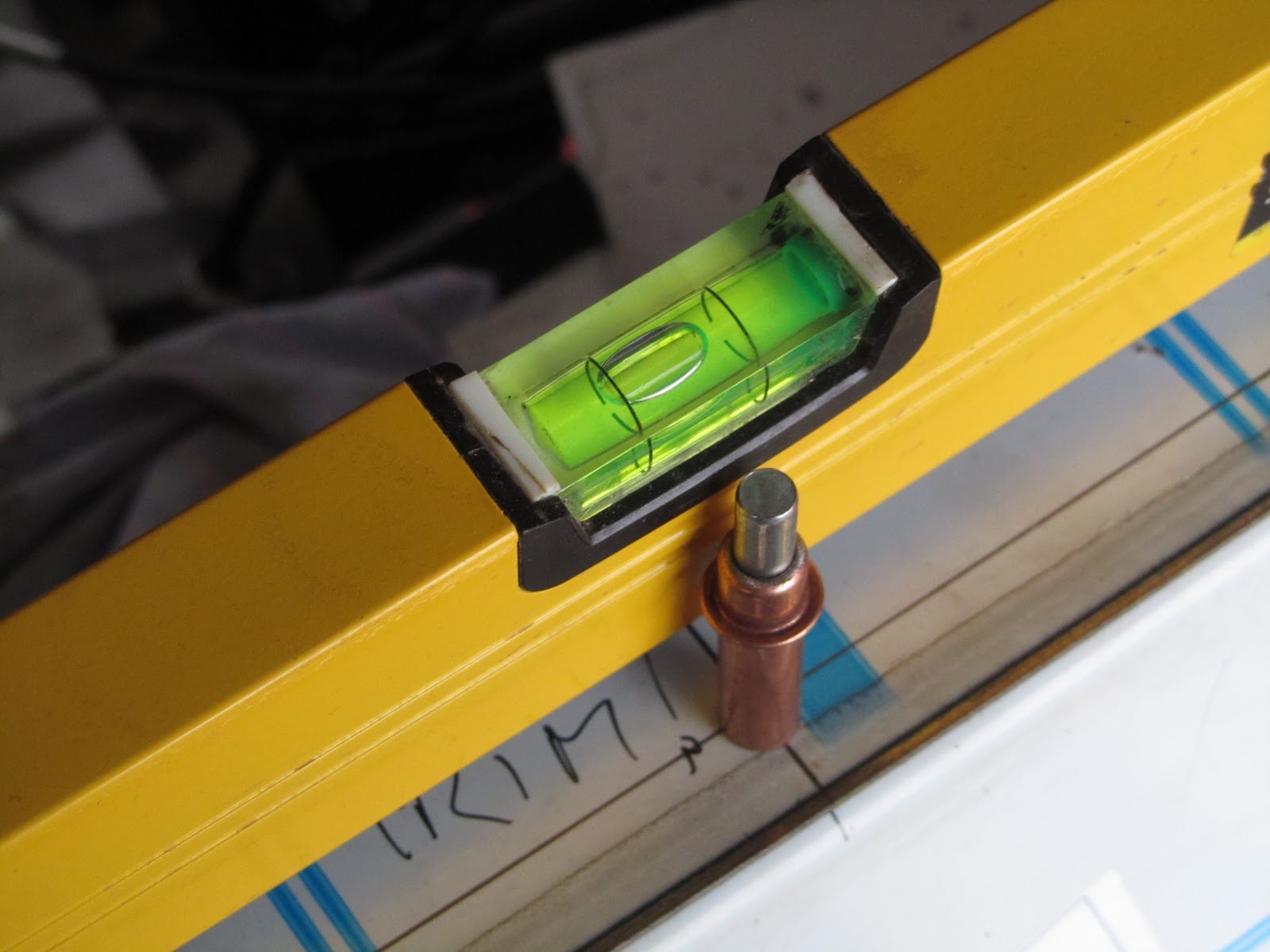
I tried out mole grips on the other bottom edge, there wasn't room for a straightedge, but the mole grips give a much tighter bend. I used a couple of strips of steel on the wider tabs to effectively widen the jaws of my grips. I checked an offcut of trim against my folds to double check I was getting a good enough result, i.e. to ensure the folds are tight enough to be hidden by the trim when I come to do the top edge.

The technique appears to be pressure towards the bend point at the same time as making the bend.

Not a bad job, just care on each tab to get the nose of the grips a little back from the fold point. The burned plastic is residue from laser cut when the panel is manufactured - it will be peeled off once everything is installed.


Bending the ends

Next up is bending the ends inwards to form side panels. I have the GT/Wide chassis so these only go as far as the high point on the wheel arches. I tried a technique I have seen on other builds, using the rear shroud panel inside the rear panel as a former for the curve. It wasn't working for me so I removed it.

Slowly bending each side up, I found a rolled up old towel useful for putting pressure inside the corner as I was bending, it seemed to help avoid creasing the metal due to too much localised pressure. The floor panel (vertical at the back in this picture) also needed bending inwards a little more - there is a locating hole on the top tab, and the sides to line everything up.

Note - The bottom two holes on the sides are to mount the diffuser, the small hole in the last tab of the floor lines up with the single smaller hole on the side panel.


I think the next step is to offer it up to the rear of the car - which I suspect will be easier if I raise the chassis on axle stands and take of the rear wheels. I'm also going to check some other blogs re position of rivets.

I have never done anything like this before so pretty happy at how it came out!

Engine mount brackets prep

The engine mount rubbers need the lugs removing, these look like rubber but actually have steel plates inside (I found out the hard way) so I used the angle ginder to take them back flush with each face:

Checking the rubber mounts against the chassis brackets the threaded rod was just protruding, I decided to cut off 2-3 mm so it could be tightened without hitting the chassis beneath, before & after pictures:

All ready to go:
 

I was intending to bolt these onto the engine, but I have to wait anyway (see clutch bearing issue) & it might be better to bolt on the brackets after the engine is lowered into the chassis.

Friday, 3 August 2012

Raceline Sump install

I already prepared & assembled the sump kit here: Raceline sump preparation

The engine is new and has the original unused oil which needs draining: I may well put this back in later and use for running in Actually ended up changing the oil for 100% fresh:

18 bolts to remove the lower pressed steel sump, it took a little levering off to break the seal & its very easy to miss a bolt!

This reveals the pickup pipe which is removed, 1x bolt & 2x torx bolts:

Removing the pickup pipe allows unbolting the main sump, I re-used the engine tray so it didn't drop to far:

Then install the new Raceline sump. Before offering the new sump up I made sure the old sealant was completely removed - there is a blob in each corner on the block where the end plates are bolted on.

A bead of loctite 5922 gasket material outside the rubber seal, especially at the corners to ensure a good seal then lowered the block carefully onto the sump, checked the flywheel end of the block was lined up and gradually tightened all the bolts. Centre first working towards ends tightening a little at a time:

All the bolts are eventually torqued up to 18 lb/ft as per Raceline instructions. Its really difficult to get a torque wrench in, but feels like the larger risk is over torquing and stripping threads than under torquing. I had lowered the engine onto my toolbox just enough to stop it spinning around as everything was tightened:


My heath robinson gripper to remove the large oil filter made from the lifting strap & mole grips. I didn't quite resort to the screwdriver through the case technique, but did manage to dent the old filter in the process. This is replaced with a shorter profile filter (no picture)

Back down on the deck to let the gasket sealant cure a little overnight then I'll put the (Fresh New) oil back in:

The install went exactly as described in the Raceline instructions, the only hairy part is having the engine dangling on the end of the engine hoist; and the acid test yet to come when the liquids go back in & I find out if I have any leaks.

The engine has to wait now for a replacement clutch release bearing from GBS. Then I can attach the gearbox and think about installing it in the chassis.

Breakage

My engine dollie which I managed to kneel on and snap the chipboard - I might rebuild it.

The oil pan I bought,  leaked from the smaller cap - I tightened it to stop the leak - and it split the cap completely. Pah - hate plastic!

Monday, 30 July 2012

Gearbox bell housing & clutch release

I didn't want to try and fit the sump on a quick evening session, I don't want to be stuck part way through that job with the engine on a hoist & have to leave it overnight.

So on to a smaller job - I thought I would mark up the bell housing cut out & some little jobs on the gearbox assembly.

Pivot change

The GBS solution to getting the correct throw at the clutch release bearing is a change to the pivot point - the old one (smaller) is removed by tapping out from behind, then the new larger one tapped in - using my 'wooden dowel' drift and a hammer:


Clutch release bearing & arm

Unpacking the release bearing I ran into a problem - it looks like it has suffered in transit/packing. The broken edge doesn't look terminal, however this part is approx a £20 value & is engine out time if it completely fails. I'm going to have a chat with GBS, but think I am going to invest in a new one.

Rats!

Offered everything up to check the fit & new pivot position, then removed until I get the replacement release bearing:

Bell housing adjustment

I marked up the required change on the bell housing, I'm going to double check some other blogs before cutting - the second picture shows two alternative cut lines, the higher one starting at the point the bell housing changes from straight to conical:

References:
    Phil Howard's build
    RHOCaR topic
    RHOCaR topic #2
    RHOCar topic #3 + picture of starter mount change

From these references it looks like my line needs to be parallel to the bottom of the housing, rather than across the corner as I have it marked.


Then I thought: If the gearbox, for any reason, fell off the bench its going to fall on the car and break something permanently - so its now sitting on the floor.

The sump is sitting under the pink sheet to the right - clean and dust free. I really want to install that first before doing any cutting since aluminium dust/shavings will go everywhere when I cut into the housing.

Sunday, 29 July 2012

Raceline sump preparation

I'm not quite ready to complete fitting of the low profile sump, I need to drain the engine of oil so need a 5 litre tray for that. However I could prepare & assemble the new Raceline  sump for fitting.

This wasn't a cheap component, but the only option unless I was prepared, or able, to cut & re-weld the OEM sump. Its a well made kit so certainly don't regret the investment.

First job was to clean everything & make sure there was no production swarf or other remnants left. As per instructions I sluiced through and washed out with warm soapy water. This did find a number of filings especially around the baffles and in the corners of the pan:

Fitting the oil pickup with its o-ring seals, finger filter & the sump gasket. They all just push into place, then the oil pickup has a securing bolt to the bottom of the pan. The gasket is keyed at either end and can only go in one way.

Everything was left to completely dry out from the cleaning at this point.

Two tiers of windage trays. Bolts, lock washers and Loctite on the first one, then standoffs (two of which are keyed) bolts and Loctite on the second. A little challenging to torque the 4x bolts on the curved part of the windage tray, I don't have any hex drive attachments for my socket spanner. They all have thread lock & tightened to 20nm.

Some more tools required before I can go further, 32mm socket so I can tighten the plug on the filter, a wide opening adjustable spanner (for various jobs) & a 5 litre+ oil tray for emptying the engine.

Friday, 27 July 2012

Toss a coin..


A few reasonably challenging jobs come next:
  1. Sump replacement - dangling the engine on the hoist <- This first
  2. Rear panel fitting - first major panel bending
  3. Chassis/Engine loom adjustments - tease out wires for FIA switch & inertia switch

I'm not sure which one tackle next...

Turns out I didn't order the rear panel fixing kit - 4x button head bolts/nuts etc - that might be an excuse to wait for an Ebay order of same and do the sump first?

I don't have a large enough socket (or spanner) for the new sump drain plug & no large capacity oil tray to drain the engine - I can probably prep the Raceline sump kit though.

Spigot bearing

To run the engine lengthwise rather than transverse the crank end needs a small spigot/needle bearing inserted which the gearbox shaft rides in. You could probably just about get it into place without removing the clutch - but its easy enough to remove and re install.

6x bolts on the clutch remove the housing and pressure plate:

The spigot bearing is inserted, rubber seal (top in this picture) facing outwards, to stop ingestion of debris/dust from the clutch.

It is carefully driven home with a hammer & drift (I have a 5cm long wooden dowel which did this perfectly):

I bought a clutch alignment tool which grabs hold of the clutch casing and clutch plate and keep them all central during mounting. Taking care to keep the clutch plate the same way round - it has a front &  back. 

Hindsight - I could probably have attached the tool before removing the housing to keep perfect alignment, its easy enough to line up the clutch plate by eye though.

6x bolts, they have splines on the heads to stop them shaking lose, torqued, alignment tool removed and all set:

The engine crank shaft actually rotated slightly whilst loosening/tightening the clutch housing - so good news anyway, its not seized since it was manufactured 8 years ago in Feb 2004! :)