Wednesday, 14 August 2013

Immobiliser

Everything back together for a test  - the circuit I have been adding was a simple immobiliser which cuts some circuits unless another electronic key is used to disable it. It is auto arming, as soon as the ignition is turned off it arms itself and has the ubiquitous flashing led to show its presence:


The intention is to guard against simple hot wiring of the ignition. If someone starts to take the bonnet off or get in the back of the fusebox (good luck with that rats nest), or simply tow the car then all bets are off.

Hopefully though it will stop a passing opportunist joyride attempt and give me a little more protection than the stock Ford ignition key barrel.

I'm not posting installation details for obvious reasons.

Fuse and Relay identification

Back from summer holidays;

Theres no circuit diagram, even for the stock GBS Zero loom, that I know of - so to add my couple of circuits & while the fuse box was disassembled I took some time to trace out fuse and relay functions. The relay functions were cribbed from a picture on DC Tough's pictures then confirmed with circuit testing:

My fuse box is mounted upside down with fuses on top, so flip this if using it on the standard layout. The lighting circuits are not of interest so I didn't fully trace everything.

Top 3 rows of fuses are permanent live feed, the bottom row controlled by the Aux relay. All 4 left hand columns are fed by a bus bar so is straightforward to use some of the spare slots.

This is the ECU power arrangement, pin 11 is driven directly from the ignition switch, pin 28 via the ECU relay which in itself is also controlled by the ECU from Pin 4:

Touch wood everything will still work when I put it back together!

Upadate - Some re-identification and extra circuits added later.

Saturday, 27 July 2013

Fuse box - adding circuits - found the part numbers

I decided to take the dash off once more to:
  1. remove/replace the wiper motor cir-clip which I weakened when switching the park position (twice :)
  2. Add a couple of circuits for my speedo project and engine immobiliser
For the second of these I really wanted to add the circuits into the existing GBS Loom fusebox rather than inline fuses. There are plenty of spare sockets with live feeds from the bus bar, they just need fuses and the right sort of spade socket on the other side of the fuse to take the live line.

This is my fusebox - mounted upside down vs. normal builds due to my slightly different wiring route under my heater. In the fuse area you can see plenty of spare slots many already with 12v feeds on the right hand side of each fuse socket:


Its stumped me for months finding the right part (even consulting GBS didn't turn up a clue)  - but just as I was deciding to jury rig a normal spade connector I chanced upon a picture of the box on someones unrelated forum from a circa 2010 entry, he had a screen shot of the catalogue page...

The GBS stock fusebox is a Delphi part a 'modular fusebox' on/around page 7.2 of the Catalogue

I need to double check but it looks like:

   Fusebox is part #12191544 on page 7.8

   Fuse cover is part #15324032 on page 7.8 

   Pins are part  #12160636 on page 7.4 15mm centreline


Result!

Update - Ordered from Mouser (I couldn't find the part anywhere else), + a locking bar and fuse cover, just to mitigate their high shipping costs.

Update - Order arrived, I can confirm the above part numbers are correct.

Thursday, 18 July 2013

Bonnet vents

Miles on the clock

My round trip to work is 84 miles, so over the last couple of weeks taking in the Zero now and again plus some spins out with colleagues at lunchtime has helped push the total milage past 1000 miles.

Good testing - need to keep an eye on the limited milage insurance though...

Everything has been fine, even in the summer heat & stop start of the M25; engine seems happy and the cooling system is just about able to hold the temperature when in standing traffic. The one big notice though is the engine heat has nowhere to go except finding holes in the pedal box into the footwells and down through the transmission tunnel to slowly cook the driver.

Vents

I'm fitting some bonnet vents to try and give the hot air an escape route and hopefully make things a little more comfortable when driving. I mocked up some options:


Eventually deciding on the last option: two or three small discrete vents on the trailing edge to also have mesh behind when I find the right product.

The sheet metal punch ordered and arrived from Ebay, it winds up with an allen key & punches through the stainless as if it was paper. First up a test on the bonnet cutout to check/confirm which way produces   a clean cut & that I'll end up with a half decent job. 20mm punched holes joined to make the slots:

Then on to marking up the offside. The slots are 20mm high with 10mm spacing. 
Drilling pattern is 4mm pilot holes, widened to 10mm then followed by the punch itself:


Holes all set:

Joined the dots with the Dremel cutting disc & then tidied & de-burred  with one of the Dremel stone wheels & sanding drum. Looks pretty much as expected, this has just been wiped with WD40 to take off the masking tape glue - it will get a proper clean when back on the car:


Both sides done & bonnet back on - all set pending some grille arriving to sit behind the holes. They're not right at the top so won't directly let the hottest air out but might setup a flow under the bonnet from the radiator and at least start moving air through:


Update - I've been out a couple of times in similar heat - nothing definitive, the holes make a some difference - nothing dramatic - good job they look good! I think the next step will be wrapping the exhaust under the bonnet and/or even a vent in the top of the nose just behind the radiator.

Friday, 12 July 2013

Debugging the digital speedo

Its Sunny !

The British summer turned up and the weather has been good for driving, so while there are over 800 miles on the clock now I've made no progress on the roof. 

Reminds me of an old cartoon in my favourite childhood book: Story Book Dictionary -now- Best Picture Dictionary Ever  by Richard Scarry

One of the Busy Town animals has a large hole in his roof:


Wow - just thought - theres my '80/20' rule or 'Good enough' lifestyle choice right there - learnt probably before I was 5 years old ha!


Digital Speedo Circuit Design

The circuit itself is cribbed from a number of forums existing projects etc & I found some great online tools for checking & drawing circuits:
  Circuit Lab allows full simulation over time & 30 day free trial
  Digikey Scheme It allows diagramming for free\

My current circuit intention is something like this:

S1,S2 - Front panel momentary select & reset buttons
R1,R2 - 5k6 pull-ups for the I2C bus
R3,R4 - 10k pull-downs on the switch inputs
R5,R6 - 200R current limiting on the 12v sensor inputs
D1,D2 - 5.1V voltage limiting Zener Diodes on the 12v sensor inputs

Mocked up currently looking like this:


+5v will be via a solid state regulator to drop me down from the car's 12v line

Inputs are 12v current and voltage protected with resistors & Zener diodes.

The illumination input will be to turn the brightness down rather than up - i.e. when instrument illumination is on its dark outside so I want to avoid glare from the LED display; not yet even mocked up.

The display is from ByVac and accepts an I2C/Serial input so I don't need a rats nest of wires/pull-ups to multiplex the 4x digits or continuously refresh it. In theory I2C bus can support multiple devices on its two wires so I could upgrade to a small LCD, Multiline or any I2C output device.

How long does debugging take...

Its been a while since I coded anything, its pretty good fun though;

I think I read somewhere (I could have the numbers completely wrong) you can write about 4 lines of bug free code a day - not through slow typing, just because debugging takes time. Arduino tools are pretty basic too, the debug cycle is to embed print statements in the code, download, run, monitor the serial output - no single stepping :/


Some progress though - the project has expanded & I now have basic menu code working for functions with two input buttons: select & reset. The functionality will be:
  • Speed - to 10ths of MPH
  • Selectable speed warnings at 30, 50 & 70 mph
  • Trip 1 & 2 - to 100ths & 10ths of a mile respectively
  • 0-60 timer - starts when the car starts moving or red button pushed
  • 1/4 mile timer - starts when the car starts moving or red button pushed
  • Calibration - on the fly tweak speed up/down & entry of pulses per mile - could even drive this via the USB/Serial input i.e. console base calibration.
  • Sense instrument illumination to adjust brightness

I'm trying to tidy up the timing code for measuring speed based on the time between bolts passing the speedo sensor but its been hit & miss without a proper function generator to test it. I have this rudimentary pulse generating code creating an output on one pin which I feed back into the sensor pin - hence that flying wire on the picture above taking the output back to the sensor input.

Unfortunately - up to a point - I am a perfectionist with code, keep tinkering, re-arranging, checking until it both works and looks pretty.


Update - the digital speedo is on hold until the dash next comes off and I add circuits - which wont be while the weather is so good!

Sunday, 30 June 2013

Hood fittings

Just a little progress, some practice with the fabric I picked up; 1000D PU Cordura & M75 thread.

The seam of choice would appear to be a 'flat felled seam' same as on jeans etc & my practice runs came out ok. This shows the detail on the fabric; matt Cordura finish on the good side with a waterproofing coating on the back:


I made my life a little difficult by not wanting poppers on the front edge of the screen - the leading edge of the hood will have a 4mm ali rod through it and held in place at three points by smaller brackets. The progress today was to work through the design of the bracket to hood fixing; with a couple of mockups and final paper pattern:


These pockets will sit just under the hem (upside down in this picture) which has the leading edge ali rod & stop it riding up:

Still not quite decided if I need a separate cut for the windscreen surround or try and make it out of a single piece,  no rush, just solve it one piece at a time.

Using contrasting thread might come back to bite me, but its got to be worth a go; provided I'm reasonably neat with the sewing it will look great.

Update - the half hood is on hold until the weather gets worse - too busy driving the car at the moment!
Friday, 28 June 2013

Projects in progress - half hood & digital speedo

Half hood

I have a couple of projects progressing currently, the first a half hood - awning type cover. I'm going to give it a go myself. Materials are already ordered from Ebay some Cordura fabric & thread; Today I worked on a simple model of the windscreen & roll bar to start to identify the shape I want & start to get a feel for the cutting pattern:

Granted paper & fabric don't behave the same way - but it helps to visualise the situation. I have slightly different fixing points to the norm, I'm not going for a line of poppers along the front of the windscreen surround:

I've not really done any work with fabric before, so no guarantee this will work; I think the next step is a mock up with some old sheets to work out a cutting pattern:

Digital Speedo

My other project is a digital speedo. Nothing wrong with the Smiths clocks I have, but I'm used to a numeric speed readout to keep on the right side of speed cameras & average speed checks.

I confirmed with Smiths that the existing 'bolt detector' speed sensor can drive another unit, so I'm playing with an Arduino Nano board and LED 7 Segment display to see what I can come up with.

My display driver is written so I can display text & fixed point numerics, Frequency measuring code also written for frequencies around 3-300hz = 1-100mph down to 10ths accuracy & I have the basic sensor circuit in place to drop the 12v sensor signal to 5v. I could do with a frequency generator to fully test my code - so either I need some more code for the Arduino to generate a known frequency using a spare clock and output pin or or hook it up to the car and see how we go.

The trick, I suspect, will be adding the right level of averaging/damping in the code to get a stable/usable speed display:

There is lots of potential here for an accurate distance/trip meter, 0-60 acceleration clock, lap timer etc

All just work in progress so far.. just depends if my mood is debugging code or sewing as to which makes progress next.

Monday, 17 June 2013

High level brake light

Minor mod; addition of a third brake light, this is a LED unit but 12v rated so no need for extra resistors it wires directly into the loom. I took the +ve line to the brake pressure switch under the boot floor with a piggy back spade connector & the ground to the rear loom ground point.

I'm using a Carpoint 1510090 28 LED light unit, some of these lights also have a little 'stop' sign in the middle, I got one without & covered its mounting holes with a little black plastic. so should be reasonably weather proof. I also adjusted the mounting feet by removing a little of the rubber adhesive pads so it sits a little better on the round tube. The light is designed to fit on a rear windscreen or parcel shelf so will rotate - thus even though I did my best to mount it vertical - the angle can be tweaked up/down to aim the light correctly.

Mounted with 2x M4 bolts into tapped holes in the roll bar + the adhesive pads that come with the light:

I wanted to hide the wiring as much as possible so routed through the roll bar with a grommet either end to keep things tidy. For the exit point I couldn't see a straightforward way to drill a hole in the underside end of the bar without removing the offside wheel & shock, even then its possible there is no room for a hole - so instead discretely took the wire out just behind the drivers seat and down into the boot space, fished through with some garden wire:

Testing - all looks fine & a little more visible in the eye line of following cars. TBH my experience so far is most cars keep a wide berth behind - theres always the type that likes to sit on your bumper but most people give you plenty of room.

I did think about the option of a flashing unit - which can be added into the loom - it seems like its only legal in the UK if it flashes during emergency stops so decided against it.

Friday, 14 June 2013

Wind deflectors

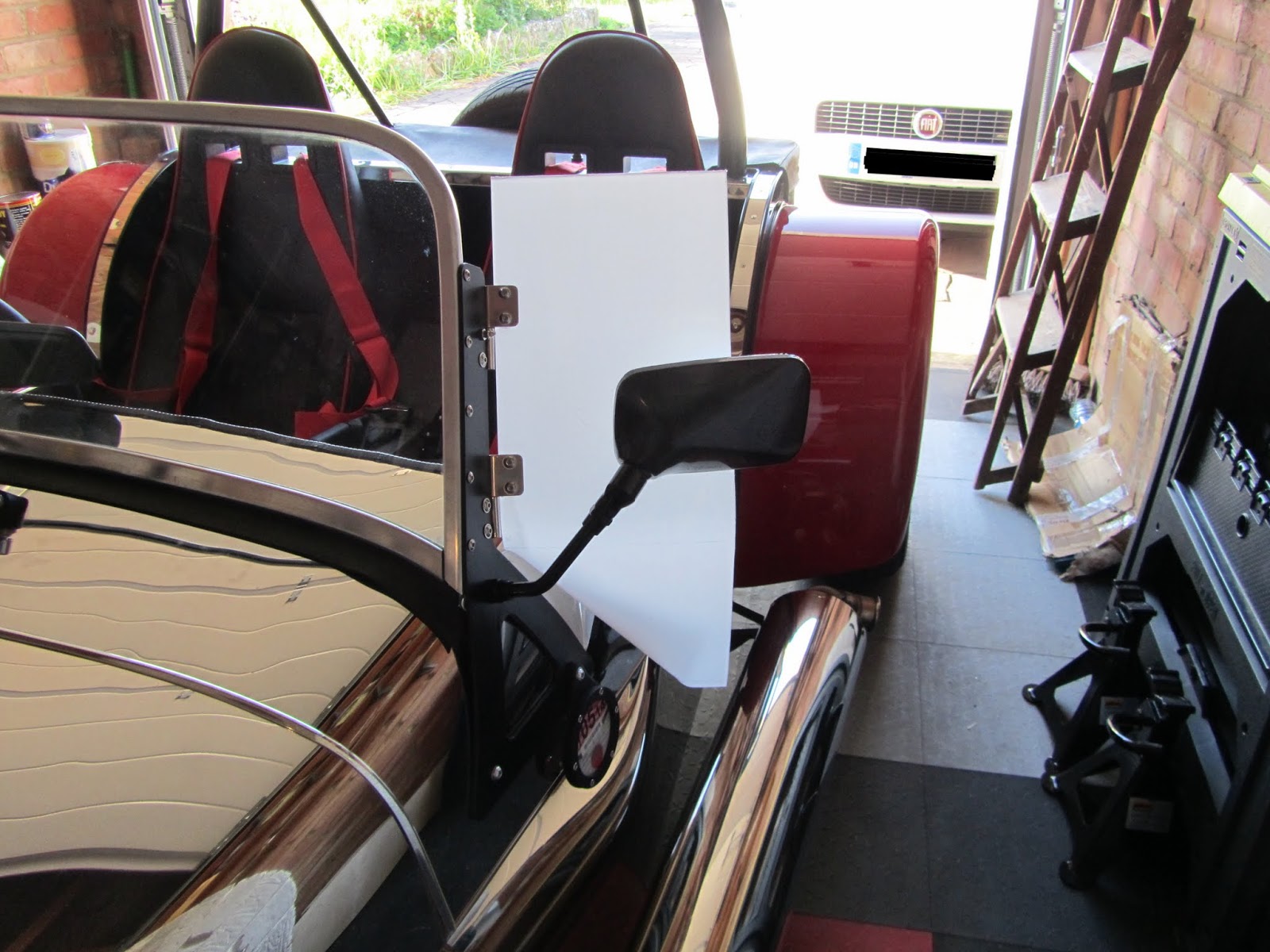
I thought I'd try and make some wind deflectors & after consulting on RHOCar for some examples and experience the advised material was PETG, easier to work than acrylic and less brittle than Perspex. I was expecting to have to practice so bought a piece 1m x 500mm  x 4mm thick from Ebay.

I had a couple of goes at templates to get the right shape and for now ended up on a simple rectangle around 500mm x 180mm with folds in appropriate places, transfered the cardboard shape to the plastic and cut out with a jigsaw; installed the hinges held temporarily by the bolts only so I could test the fit on the windscreen frame.

The PETG will bend with gentle heat from a hair dryer; so I rigged it up to bend under its own weight and a little persuasion from some scrap wood; it produced more gentle corners than I was expecting:

First couple of fits got me close:


Then for final fit I removed the covering anti-scratch film and bolted the hinges in place, for now I think I'm leaving the very basic rectangular shape:

Finally I worked the bottom edge against the scuttle shape with more heating and gentle pressure:

My daughter volunteered for a test drive & she said It makes a difference, a little less blustery than before - so next up will be making a similar one for the drivers side. It does seem quite a soft material so I'm not sure how it will stand to scratches, but nice to work into any shape.

Update - While they don't stop much wind the deflectors are invaluable in stopping the front wheels firing whatever they drive over into your face, the angle is just perfect to project any debris around the windscreen pillar at you or the passenger - be it mud, water etc the deflectors are a really useful addition to the design.

Update - These were replaced with a newer design here, and then later I reverted back to these.

Update - Replace in 2017 with acrylic versions to match the sun visors.

Saturday, 8 June 2013

Sunny Day - Gallery

Sunny day - shiny motor @ Dad's house:


Perfect opportunity to use a picture of my own car for the blog header.

A good run out, 88 miles round trip (its 70 miles by the map, the other 18 were a scenic route to enjoy the car), I got some practice in negotiating speed bumps & made a note to adjust the rear ride height - its a little low right now meaning the seat bolts ground on speed bumps & smaller road bumps & the offside rear tyre touches its wheel arch.

I think she is doing something like 20mpg - keep in mind I wasn't holding back with acceleration, so thats not too bad either for the stock Powermap, certainly no rush yet to get the ECU tuned.