Showing posts with label radio. Show all posts

Saturday, 12 August 2017

Sena SMH5 intercom

More prep for a passenger on the Vienna run, time to finish the intercom modifications.

Components

I'm using a Sena SMH5 motorcycle intercom installed on Howard Leight LO4 shooting ear defenders. The SMH5 is an older model - trying to hit the sweet spot between functionality and price + this version retains the large jog wheel rather than push buttons for volume.

Functionality

- Stereo sound
- Intercom
- Bluetooth audio in from any source
- Music sharing - one headset feed from the radio can share with the passenger
- Phone audio in/out
- Runs from battery, but also functional while being charged from USB 5v - so I can charge it on the run.

The radio is already modified to transmit on bluetooth so this change means I get my default music playback + with the push of a button can talk to the passenger. As a bonus it will also talk to my phone - but thats a mixed blessing - when I'm driving the Zero the last thing I want to be doing is taking phone calls!

Installation

Mods to the ear muffs filing out some grooves to route the wires.

The right ear speaker cable is looped over the headband and secured - one stitched, the other glued. Lets see how robust Gorilla glue really is.

The speakers sit inside the ear muffs attached with velcro, the ear pads clip in - so can be removed for routing cables and re-installed to hide them.

Controls Reference


On the bench and stationary in the garage functionality checks out, needs a test run.

The mic boom attachment may need some adjustment - by design its meant to have another support around the chin area in a helmet which I cannot provide, it may need its velcro fastening replaced with a 3M sponge pad or some 3M dual lock. 

Saturday, 19 November 2016

Radio noise suppression & bluetooth headset

Ground Loop isolation

Testing the new bluetooth output from the radio I had some ground loop noise.
Two options:
   - Isolate the 5v feed to the bluetooth board
   - Isolate the audio connection from the radio to the bluetooth board

I went for the second with a cheap off the shelf component which installs between the radio cable and the bluetooth card. No power required - inside are a couple of audio 1:1 transformers for left & right channels.

Does the job - audio is now crystal clear. 

Headset Mod

I bought a pair of Sena SMH5 intercom units, designed for installation inside a motorcycle helmet. Selection of SMH5 vs 10 is a combination of price, due to being an older model, nice prominent rotary volume control and physical size. They will also work when charging via a 5v USB cable which means my pet hate of flat batteries is not a problem.

SMH5's can pair to each other - for standard intercom functionality as well as mobile phones and receive a bluetooth audio input. I think although have not tested they should be able to also share the bluetooth signal - so the single transmitter installed in the radio should provide audio to both passengers.

The first one is installed on a Howard Leight L0f earmuff. Selection being a combination of price and quality - they are thinner than my existing wired earmuffs but perfect for modding. The SMH5 sticks to the outside and cables routed over and sewn to the headband, speakers stick inside to the earmuff padding.
I didn't want to detach the speaker cable, it is very flexible and thin & dont fancy re-soldering the stereo wiring inside - hence routing it outside the headband, this approach also means I have not damaged the SMH5 in any way - warranty FWIW intact.

The loose cable is for the microphone arm to be installed later.

Update - completed these headsets much later,  sometimes life just happens and the car takes second place!

Sunday, 23 October 2016

Radio hack - bluetooth transmitter

The new wireless intercom allows a media input channel via bluetooth.
The radio is intended to be useful but also: too boring to nick and have minimum of openings/semi weatherproof. The quickest way of adding a bluetooth output appears to be modding it slightly.

Around a fiver buys me a rechargeable bluetooth Tx which charges from a 5v USB supply.
As soon as it sees USB power the unit starts up in pairing mode without the need for an on/off switch. I don't need the battery (nor want a LIPO in the car) so that is removed and I'll just drive it from the USB power input.

Plenty of room inside the Blaupunkt Melbourne 180 - its the shortened version and has no mechanical CD drive. It has both SD card and USB file inputs - the latter means there is 5v on the circuit board easily traceable from the existing front panel socket and on reasonably sized solder pads.

Patched in mini USB cable on the back of the front panel to feed GND and 5v

Mini Phono patched into the rear C1 connector giving me a line level audio feed.
Even though it is called line level this radio drives it through the volume knob, so still some gain control via the radio.

...all assembled, hot glued in place and hot glued strain reliefs on the new wires. The bluetooth module stuck to the front panel which hopefully helps its range. When the radio turns on, so does the bluetooth module which immediately looks for an existing pairing then streams whatever the radio outputs.

Update - later addition of a ground loop isolator to suppress audio interference

Final mod - a 15mm grommet on the volume knob so its easier to get a grip on when driving and especially when wearing gloves.

Monday, 19 September 2016

End of season - To-Do list

Getting towards the end of the good weather and driving season with a certain autumn feel now in the air. I'm starting to compile the winter to-do list. Some are already started with parts ordered and just waiting for enough bad-weather that dash/off is unlikely to remove any driving opportunity:

1. Intercom II
The new intercom approach, financed by a little selling on eBay, is a combined shooting ear-muff + motorcycle bluetooth intercom hack. Intended to avoid shouting between driver and passenger. The radio will also have a simple Bluetooth transmitter added.

2. USB Power
Replacing the existing single 'lighter socket' with a couple of purpose built twin USB power outlets
The front socket is permanently used for camera and sat-nav anyway.

3. Aux Panel buttons upgrade
The savage switches will be coming out to be replaced by something more robust.

4. Suspension height + brake disc paint.
That feeling when the seat bolts bottom out on roads with a high camber needs correcting with a turn on the rear adjustable coil-overs to stiffen things up a little. It's probably a combination of the springs settling and me getting heavier - or driving faster :) . I think I'll paint the slightly rusty/visible parts of the brake discs while the wheels are off.

5. Wideband Lambda
Some discussion on Facebook + identification of a new (to me) piece of Wideband lambda kit. It can null out some inaccuracies caused by installation, loom driven voltage variances, and looks interesting. Intending to swap out the narrowband (parts not yet purchased for this one)

6. Clocks surround + Shift light
I must get around to removing the stainless clocks surround and changing the mirror finish. I think just a brushed one will do the trick and stop it reflecting the sun right into my eyes. This post on Mitch's Blog reminded me. Installing a combination shift light and indicator tale-tale while the dash is apart.

None are must haves - just tinkering/upgrading.

That should keep me busy!

Sunday, 21 February 2016

Because - tinkering

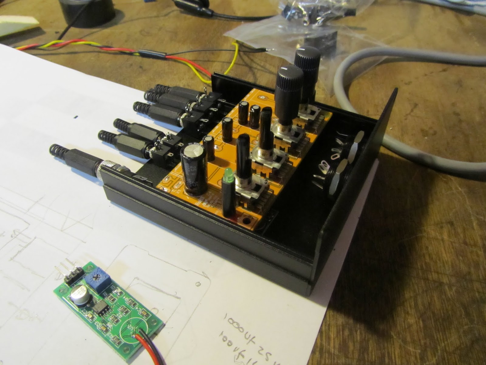
Part way through a little project - adding multiple headphone outputs and mic inputs to the existing FM Radio/SD card player system.

Motorcycle or Rally intercoms can all be bought off the shelf, for a price. 
I'm more interested in tinkering and dismantling/hacking/integrating a few existing components to see what I can come up with. Wireless is overrated IMO - just more things to charge up!

The Schematic

The principle is to leave the audio route from main Head Unit to speakers and rear headphone jack alone since that works well.

Dotted line is the new unit, double arrows stereo paths, single arrows mono paths.

Green boxes are off the shelf components hacked slightly and integrated, Red - switches, Yellow - built up components etc. Two Microphones will switch in via a relay which also mutes the head unit via push to talk switches. The Amplirider will mix in the Mic signal and can be powered by head unit or intercom box depending which is turned on.


The build

Must clean up the bench!
Mic Amps mocked up and tested, currently working out the layout for the case

Layout should work:
    Output stage is a modified Behringer HA400 Headphone amplifier,
    Input Mic Pre-amp boards from an unbranded Ebay source
    Buck/Boost Power supply to provide stable 12v, again Ebay

Biggest expected challenge to be potential ground loop issues and wind noise in the Microphones - can't be any worse than the current drive/passenger 'shouting at each other' mode of communication.

More detail to follow.

Update - This approach was not completed, I invested in a motorcycle intercom and went wireless instead!

Wednesday, 17 February 2016

Broke the 2016 Duck

Broke the duck and despite the cold, but dry, weather took the Zero out for the first spin of the year.

South through Kent & East Sussex: Towards Hastings, Rye, Romney Marsh, good Pub lunch at the Woolpack Inn  in front of an open fire then a convoluted route home. No sat nav, so mostly just heading sort of south until sea blocked my path then east and choosing any road which looked interesting.

A little bit of pure escapism...
Open road the chance to concentrate on the drive and when in traffic to look at the Kent/Sussex countryside view.

Gave me a chance to test out a Christmas present - some earmuff come headphones.
A pair of Howard Leight Syncs do the job nicely - passive noise protection which massively reduced wind noise and buffeting, a decent sound driven through the Amplirider and not least keeps my ears warm!

Picked up some engine oil on the way back ready for the Annual oil change (When I'm in the mood to crawl around under the car)

Friday, 4 September 2015

Headphone jack plate

Stereo jacks come in two forms, 3 pole and 4 pole, potentially compatible with each other, but only with decent quality sockets. Upgraded my socket and then ran into a problem - the new one used its case as a ground and my old bezel was Ali shorting the audio ground to the chassis.

Spent a couple of hours building a replacement bezel from an off-cut of Formica.

3-4 coats of paint and you would never know the difference; except this one doesn't ground the headphone jack and my iPhone earphones as well as the helmet speakers work properly.

Monday, 17 August 2015

Amplirider - radio headphone amplifier

Upgrading the headphone circuit. My previous attempt had a lot of noise, interference buzz/noise, at speed, probably because it needed to use the car chassis as the common ground.

The new approach is using a little headphone amplifier from a Canadian firm - the Amplirider. It's designed for motorcycles; takes a 12v feed, draws less than 0.2Amps with up to 3 line level inputs and one output.

All the reviews I have seen on various motoring and other forums on this, and its brother PA2V2, are positive with great support from the guy that builds them; so thought I'd give it a try.

Wiring

My Blaupunkt Melbourne head unit drives its line out pins as a pre-amp still controlled by its own volume knob. All accessible from the Mini-ISO C connector: it has a 12v feed, common ground alongside the stereo line levels. So relatively simple wiring on the input side - the Amp will simply piggy back on this port.

Doing a little reading on ground loops - This amplifier seems to have built in isolation on the power lines, so no issues.


The Amplirider will act as power-amp to drive headphones/helmet speaker levels. It's volume will be left somewhere around 3/4 to max.

Installation

The plan is to glue the amp in place on top of the head unit with a double sided sticky pad, no need for access to its volume knob in normal use which will be hidden somewhere around the side out of sight.

Headphone jacks

The amp output is wired to the existing jack panel between the seats.
The rear speakers retain their switch to isolate them when using only using headphones.

Much nicer sound and higher distortion free volume in static tests with and without the engine running; actually got carried away testing  & listening to various tracks/radio...

Wednesday, 15 April 2015

Radio Headphone circuit

Still faffing with the radio; which isn't audible through the speakers over about 40-50mph.

The head-unit has separate amplifiers on +ve and -ve speaker lines & with headphones taking a common ground it needs a little workaround. Connecting left and right -ve or +ve lines will upset the head-unit amps.

The solution, cribbed from googling and reading through various forums is a current limiting and AC passthrough circuit wired into the +ve side of the speaker feeds and the common ground from the headphones back through the chassis ground:

I'm also incorporating a simple double pole single throw switch which isolates the speakers when not in use. I can't use the normal automatic switching 3.5mm jack socket due to the requirements of the circuit.

Decided on a small aluminium bezel for the components:

...and in situ:

Works well enough while stationary; test will be whether its any better when moving and through speakers added inside my helmet.

Update - doesn't like iPhone headphones - the vocals almost always drop out, better response on the helmet speakers though. I suspect the circuit needs some audio quality capacitors and/or some adjustment in capacitor value. If the radio is outputting certain freqs. on the -ve vs +ve speaker lines then its a whole other problem.

It's probably the issue of having to use chassis ground in the first place - at a probable completely different potential to the audio outputs.

Update - in the process of replacing this circuit with a specific amp.

Update - re-created the bezel in formica so its non conductive and can use a metal case socket.

Sunday, 6 July 2014

Aux Panel re-install with radio & DRL

Wiring: Fusebox

New key for the fuse box, in the process of adding the new circuits I documented all the fuses. Colour coding matches fuses to those which have relays switching them: (My fusebox is upside down vs. standard Zero build, fuses above relays)


Wiring: Savage dimmer

My new preferred Savage switch dimming circuit vs the old one.
The same approach is used on all three switches with the output +ve load looped over to the LED side of the switch. Thus on the fog switch, which takes +ve from dip beam it is a true tel-tale, the switch only lighting when the fog lamp itself is lit.

No extra diodes necessary, the LED itself is a diode so won't let current back through to the side lights circuit when the switch is off and in any event its grounded both sides in this scenario.

Update - this could do with a fuse on the LED ground line, shared between the three switches.
If (when?) the LED/bulb shorts it will blow the fuse on the +ve feed - taking out headlights or sidelights fuse. With a separate very low current fuse on GND any problem with the LED/bulb will leave the primary load circuit working.

When off: 

  • +Ve feed connects to nothing
  • If side lights are on they illuminate the switch dimmed by the resistor

When on:

  •  +Ve feed connects to the load and in parallel through the LED, thus when the load gets power, the LED gets power.
  • For the fog lamp the +Ve feed is the dip beam line, so when on  with dips off then the switch LED does not light and neither do the fogs.

The savage LEDs are rated 12v so the resistor is only to dim them slightly, I used 0.6W 5k6 Ohm resistors. The resistor should dissipate approx 0.02W when side lights are on.

Aux Panel MkIII

Final steps on the new version of the aux panel, vinyl covered and an override switch top right so the electric aerial can be indepdendently turned off. My thinking is this will be useful either if it gets stuck, or more likely to ensure I don't raise it in the garage while testing the radio. 

I'm using the original sides of the old panel, the second picture showing how the front face is now a little more vertical:

I still don't have a new push-pull for the heater control in the left most position, so just a placeholder blank plate for now:

 Trying to keep the wiring as consistent and neat as possible & went back to the standard 11 way connector for the panel. Re-used the old earth rivnut for a stand-off to support the back of the radio:

With the heater matrix on the other side of the firewall bulkhead & the aux panel itself sitting slightly more vertical there is a good inch of space between the radio back and heater box:

Testing: Side lights off, then side lights on which illuminates the switches, radio volume button(when its off) or dims the radio display when its on:

The Radio did give me one gotcha - it takes two live feeds, one permanent to maintain its memory/time etc, and one via the ignition to allow it to turn on - I wired up exactly as per the manual using the standard ISO connectors - but it turns out this particular radio needs these two feeds reversed to work properly - go figure :)

Update - after talking to Blaupunkt, turns out the radio when wired as standard will turn on when ignition is off but only for 1 hour. So currently wired to not come on at all - may change it back in the future.

And my nifty (although already temperamental) electric aerial. It works well as an aerial, and I like the way its hidden when not in use, however it also has a habit of not quite winding all the way down - I'll pull it apart and re-grease/clean etc at some point:

Daytime Running Lights

The DRLs wiring installed now, switchable via the aux panel. I bought a switching box which takes +Ve, Ground and a feed from the side lights to automatically turn the DRLs off, overriding the panel switch, at night time when the side or headlights are turned on. The 6 lights just below the headlights actually look brighter than this in bright daylight - very pleased with the effect.

More noticeable in these later examples; my Zero is in the far distance on the first with only DRLs on:


Took her out for a test drive to Ashford on the M20 and back on the A20 ... :)

Passed a couple of huge articulated lorries near Maidstone, a matt black Pirelli & a Grey/Silver one possibly Mercedes, presumably on their way from the Silverstone F1 Grand Prix today heading to mainland Europe.

The radio is much clearer, no distortion now at high volume - but still really only useful when waiting in traffic or moving under 50mph, after that buffeting takes over and all you can hear is wind - I'll add in a headphone circuit later.

Over 50mph there is more to concentrate on anyway!

Final part of the upgrades is the holes in the bonnet to let air into the heater matrix. I need to be in a calm mood for that one - no second chances.

Sunday, 29 June 2014

Radio wiring & Aux panel fabrication

Radio Wiring

Inside the fusebox was off to add in a fuse for the electric aerial. It has a permanent live feed to let it wind down when the ignition is removed so I thought it best to have an independent 5A fuse. The polyswitch is also removed now in favour of a separate fused circuit direct to the battery for radio memory & immobiliser flashing LED. My cutoff switch cuts everything except this single radio memory circuit.

Not much to see when its back together - its not the easiest of jobs wading through the back of the fusebox, especially as everything seems just out of arms length when working inside the car:

Radio wiring routed down the passenger side of the tunnel: aerial, electric feed to raise it and the speaker cables. Touch wood it doesn't all interfere with each other - we shall see.

The aerial itself needed a grommet to prevent it earthing against the car, and an eyelet in the boot lid to let it pass straight through when the radio is turned on:

Aux Panel

A little headway on the new Aux panel. I'm keeping the sides from the old one and just re-building the front face in 1.6mm aluminium as per the hardboard template. Then I can offer it all up with the dashboard back in place to find the right angle before riveting the sides back in place.

The folded top edge goes back on my version rather than forward on the stock GBS panel, meaning it will be a little more vertical and hopefully give some more room behind for the switches which are mounted much lower. Everything to be re-covered in vinyl once complete: