Showing posts with label transmission. Show all posts

Sunday, 19 May 2019

Diff oil check and topup

20 minute job to check the differential oil levels and top up as per normal Ford maintenance schedule.

While I'm here a look around for anything amiss but other than being dirty everything looks exactly as it did when I originally built it, no obvious wear or movement on anything.

Filler plug out which is magnetic and not looking to bad - no obvious buildup of metal here.

The oil level should be level with the bottom of the filler hole and a check with an allen key is showing I'm a little low - 2cm or so on this indication used about 250ml of gear oil to bring up to the right level. I lose oil slowly through the diff flange - a drip amounting to this top-up procedure every 12-18 months.

Dribble from the filler showing I'm full again.

Long 1m long grow-bag trays from the local garden centre are the perfect low profile drip trays under the car - the trick is to find ones without drainage holes!

Plug back in and all sealed up.
All set.

Sunday, 28 April 2019

Grease the prop-shaft

Maintenance - make sure the prop-shaft UJs are full of grease. New flexible grease gun hose made this much easier, theres not enough room to clamp on a normal gun end it needs a cone/needle attachment.

Aft requires the handbrake cable crescent removing, the nipple buried deep centre frame, fore slightly easier to access: 

Handbrake cable looked fine around the crescent, good and greasy no obvious wear.

Thursday, 31 August 2017

Prop shaft UJ lubrication

A while since I did this job, its awkward and messy.

The only way I can get on the prop-shaft universal joint grease nipples is with a needle style grease gun adaptor.


After lots of fiddling, depress the nipple ball bearing with the point of the gun and squeeze until the 'crack' and a little ooze indicating the UJ is full. Rear under the disassembled handbrake half-moon,

Front,

Healthy amount of oil in the tunnel, my diff slowly drips some out perhaps half a cup a year and keeps the tunnel area happily lubed. Visual inspection of  all the fuel lines/cables and diff flange bolts while the covers were off - all still secure, attached and no sign of chafing.

Friday, 21 April 2017

Gear selector saddle upgrade

5 minute upgrade - the gear lever saddle clip which isolates/cushions the lever from the gearbox linkage.

I was watching discussions on Rhocar replacing these clips with brass parts to tighten the gear selection. Any wear on the plastic saddle I also understand can affect ability to engage some gears - so seemed like a nice straightforward upgrade.

I really dont want to feel pure metal on metal 'zing' feedback from the gears through the gear lever. Opted for middle ground, a heavy duty glass re-enforced nylon version (red) to replace the original (black) one.

Straightforward pull out and push the new one in - making sure to maintain correct orientation. There is no particularly obvious wear on the original, time will tell if this new one makes a noticable difference.

Sunday, 18 January 2015

Prop-shaft UJ Greasing

First day into the garage this year, quick maintenance task:

Tunnel covers off and grease the prop-shaft UJs. The grease nipples are just about reachable from the top of the car but it needs a cone style grease gun end to get into the UJ cross.

While I was in there I made a visual check on the prop shaft/diff bolts and diff flange plate bolt - nothing has moved so all good.

Saturday, 16 February 2013

Differential breather check

The small drip from the differential might be overfill, might be blocked breather... might be - who knows.

I checked the breather today - all seems clear - so inconclusive so far;


Wednesday, 13 February 2013

Sieve

I thought I was building a car,  turns out every chance they get the liquids want to leave, temporarily its behaving more like a sieve :)

So far it looks like this:

Updated - 24/2/13


Diff flange plate nut - new & to be solved

I have a slow drip now from the front of the diff - not around the seal, but the end of the flange plate  near the centre nut. Its about 2-3 drops every 24 hours. The diff seals are new - I suspect its getting through the splines somehow. I also suspect I'll need to at least unbolt the propshaft to remediate it which will be fun through the top of the transmission tunnel - hopefully I can resolve it without removing the diff entirely.
Update - I think it was over filled, once I had checked the breather was clear and set the car back level its stopped dripping


Cooling system - thermostat housing - needs re-assembly

The pipes/hoses are fine, just needed tweaking on the bottom rad hose and it was all good. Thermostat housing, very slight ooze when everything is up to temperature. I suspect I need to sand the thermostat middle plate flat (seen this method on Paul94's blog) and probably add some instant gasket for good measure.
Update - Turned out it was one of the temperature sensors that was leaking & just needed tightening a little; if it re-occurs I'll re-install the sensor with some gasket paste.


Brake fluid - pending filling/bleeding

This one is much easier and expected - as the fluid goes in the various brake line connectors need tweaking. I put some PTFE around the brake light switch before I started; I've read this can leak if its merely tightened into the union.
Update - No real problems; I've yet to 'stand on the brakes' but so far everything is fluid tight with a firm brake pedal.


Fuel system - pending re-assembly

The new swirl pot has arrived from GBS & the Facet fuel pump is rock solid now, so should be good on this one once its re-assembled.
Update - New swirl pot in place and everything is fuel tight again


Engine oil

Touch wood - no issues here !


Lesson for the builder - liquids in early while there is room to work around the components. 
Not too downhearted - just need to work each problem.

Sunday, 30 September 2012

Liquids

Time to put oil in the gearbox & diff, I had been putting this off - irrationally - I just had this feeling something would start leaking...

There's just enough room to get a stock funnel into the gearbox with panels on. My Type 9 took about 1.9 litres:

The Sierra 3.62 ratio diff took about 1 litre. Its also managing to leak/weap very slightly from one of the back plate bolts, so off to Machine Mart to pickup a T45 Torx bit to give it a tweak. I'm assuming/hoping it was the one loosened to original drain the oil (before it was in my ownership):

Not much to see...


Update +3 hours: I couldn't move the cover bolt in question & its not leaking anymore... I think I'll just keep an eye on it

Update +24 hours: no leak... perhaps the original was a splash from filling?

Update +5 days: no leak... result! it must have been a splash/drip from filling


Saturday, 29 September 2012

Chassis loom - reversing light switch

The Type 9 gearbox reversing switch location leaves <1cm to the tunnel side. With hindsight I should have organised the loom/plug for it before the gearbox was installed:

The standard GBS loom comes with 2x spade connectors which are completely unsuitable. I took apart a couple of bullet connectors (Red Bullet Sockets from Maplin seem to be right), carefully bent the end at 90 degrees and covered with shrink tubing to make the appropriate connectors. Its still a fiddle to get these in place:

Saturday, 1 September 2012

Engine install

Next up - installing the engine assembly. 

A milestone job & relatively involved one having the engine swinging around for much of the operation. It would possible as a one man job, but much easier with two - my wife helped - then you have a point man to look out for clearances etc, and when lowering in the engine one on the hoist & one one guiding the gearbox mounting into place.

Oil pressure sender & underside bolts

A couple of minor installs, the oil pressure sender (on the left of the OEM ford one) & as the engine was raised up I could get access to the starter motor bottom bolt & 2x bell housing bolts. The bottom starter bolt seemed to bind part way in so the washers let it do its job without breaking something.

All ready to go

The load balancer was good at changing the angle of the assembly, I shortened the back chain to give a general downward angle. Because the chains were attached at diagonal opposite corners it did mean the engine would twist as the balancer changed its angle but the effect was minimal & could be offset with a little man handling:

Chassis first time out in the open:


First attempt

The legs on the engine hoist were the biggest liability - they are too tall to run under the Zero's front suspension which means the car needs raising. When raised on axle stands they seem to want to be in exactly the same position as the hoist legs: tried the axle stands inboard first:

Then axle stands wider under the lower wishbones & lengthened the hoist jib to maximum reach:

Rethink & Success

Finally I found the best axle stand position was just one in the middle.
We slowly edged the engine assembly back/down & adjusting the angle as we went:

The final stage I had a couple of bits of scrap under the back of the gearbox casing to guide it back at the right height into its mount. The gearbox slots into its rubber mount at the back, then 2x arms are bolted to the engine sides and sit on the 'card' powder coat protectors:

Engine in place

At this stage I have only bolted the engine mounts to the engine & not to the chassis, I need to check a couple of points where clearances are a little tight & make sure everything is aligned centrally down the car. The fuel lines on the offside currently touch the bell housing & the bottom bolt on the starter is very close to a chassis rail on the nearside:


The padding will come off as soon as everything is fixed in place, its just there to protect the powder-coat finish on the chassis rails underneath.

I still need to check the clearances & drill/fix the engine mountings to the chassis; but its essentially in!

Sunday, 26 August 2012

Mount the gearbox to the engine

Offered up the gearbox, packed up level with some scraps & all slid into place and just needed gentle tightening on the bolts to pull it home, 7 bolts in total + thread lock, carefully checking the depth of each tapped hole before tightening (someplace I saw a blog where someone tightened bolts and pushed out the casting inside the engine)

Offered up:

Fully torqued (save 2x bottom bolts):

I can't get to the bottom two bolts with it sitting on the deck - the bell housing is preventing a socket getting hold so will wait until later before installing them.

Bell housing and gearbox prep

I received the replacement clutch release bearing from GBS so all set now with parts to prep the gearbox & ultimately join to the engine.

Type 9 gearbox requires part of the starter motor bulge on the bell housing removed to clear a chassis member. I'm taking a chance - working from reference to other peoples builds and some rough measurements to decide where to cut. I'm not going to install/mark/remove the gearbox - this might come back to bite me later :)

I thought the bell-housing might be ally, but by the time I had finished the dust was plainly magnetic so looks like a steel cast iron housing. I cut through with the Dremel and the abrasive cutting discs - of which I managed to get through 6-7, especially when the cut got deep its easy to put accidental side pressure on the cutting discs and shatter them.

I emerged from this job looking like I had been mining for coal - black steel dust everywhere - eye and breathing protection a must! (See later posts, I should also have taken some off the lower start motor mounting point to clear the chassis tube sufficiently)

I painted over the cut edge with black hammerite, played a little with the original & quick shift levers to find all the gears, then went on to install the clutch release lever and bearing:

2x gearbox mounting collars go at 3 & 9 o-clock on the housing, they needed a little grinding to get an interference fit then pushed into the holes on the engine with a little help from a rubber mallet:

(To the right of the picture below you can see the window I smashed with a flying Dremel tool when opening up the spare wheel panel holes)

Minor snag - the gearbox mounting kit is 1x M10 bolt short - I think it must drive whomever packs the bolts crazy counting them & they just miss one here & there.

I need to think about plan the next steps - once I mount the gearbox to engine it becomes very difficult to move which means probably doing this just before install in the chassis.

Plan:

  1. Chassis back onto its wheels
  2. Chassis into the drive
  3. Mount gearbox to the engine
  4. Fit gearbox/engine (in the drive to give vertical room to work)

Monday, 30 July 2012

Gearbox bell housing & clutch release

I didn't want to try and fit the sump on a quick evening session, I don't want to be stuck part way through that job with the engine on a hoist & have to leave it overnight.

So on to a smaller job - I thought I would mark up the bell housing cut out & some little jobs on the gearbox assembly.

Pivot change

The GBS solution to getting the correct throw at the clutch release bearing is a change to the pivot point - the old one (smaller) is removed by tapping out from behind, then the new larger one tapped in - using my 'wooden dowel' drift and a hammer:


Clutch release bearing & arm

Unpacking the release bearing I ran into a problem - it looks like it has suffered in transit/packing. The broken edge doesn't look terminal, however this part is approx a £20 value & is engine out time if it completely fails. I'm going to have a chat with GBS, but think I am going to invest in a new one.

Rats!

Offered everything up to check the fit & new pivot position, then removed until I get the replacement release bearing:

Bell housing adjustment

I marked up the required change on the bell housing, I'm going to double check some other blogs before cutting - the second picture shows two alternative cut lines, the higher one starting at the point the bell housing changes from straight to conical:

References:
    Phil Howard's build
    RHOCaR topic
    RHOCaR topic #2
    RHOCar topic #3 + picture of starter mount change

From these references it looks like my line needs to be parallel to the bottom of the housing, rather than across the corner as I have it marked.


Then I thought: If the gearbox, for any reason, fell off the bench its going to fall on the car and break something permanently - so its now sitting on the floor.

The sump is sitting under the pink sheet to the right - clean and dust free. I really want to install that first before doing any cutting since aluminium dust/shavings will go everywhere when I cut into the housing.

Friday, 27 July 2012

Spigot bearing

To run the engine lengthwise rather than transverse the crank end needs a small spigot/needle bearing inserted which the gearbox shaft rides in. You could probably just about get it into place without removing the clutch - but its easy enough to remove and re install.

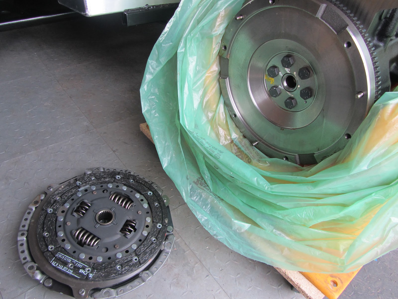
6x bolts on the clutch remove the housing and pressure plate:

The spigot bearing is inserted, rubber seal (top in this picture) facing outwards, to stop ingestion of debris/dust from the clutch.

It is carefully driven home with a hammer & drift (I have a 5cm long wooden dowel which did this perfectly):

I bought a clutch alignment tool which grabs hold of the clutch casing and clutch plate and keep them all central during mounting. Taking care to keep the clutch plate the same way round - it has a front &  back. 

Hindsight - I could probably have attached the tool before removing the housing to keep perfect alignment, its easy enough to line up the clutch plate by eye though.

6x bolts, they have splines on the heads to stop them shaking lose, torqued, alignment tool removed and all set:

The engine crank shaft actually rotated slightly whilst loosening/tightening the clutch housing - so good news anyway, its not seized since it was manufactured 8 years ago in Feb 2004! :)