Showing posts with label unfinished. Show all posts

Sunday, 9 April 2017

16v Zetec plastic badges

While I was away some ordered badges arrived, these ones are embossed plastic by a firm called Signomatic based on my original cam cover images. Similar tech to that used on shopstaff name badges and various colour combinations available.

Relatively expensive in small runs but the quality is above anything I can produce on the 3d printer, not sure yet if/when they will be applied to the car.

They also produce aluminium nameplates but too expensive for me.
The ideal would be some enamel on metal.

Monday, 2 January 2017

Wideband Gauge

Nice sitting down/post Christmas relaxing sort of project - playing with some parts to build a Wideband Lambda gauge/real time readout on the lambda sensor.

Inspired by the work of Jonas Bylund:


I'm making some modifications so my gauge will be a bar-chart and fill from lean to rich - the same direction the emerald software does and because it will give a visual representation of fuelling - more lights = more fuel. The gauge takes the 0-5v feed from the Wideband sensor and is just a calibrated volt meter to show a central 2.5v of that range.

Knocked up the simple circuit based on 3x LM3914 which do all the work, requiring only few external trims, resistors and a pullup system on the LEDs to make the display work in reverse: 5v = no LEDs lit,  0v = all LEDs lit.

Oldschool transfer to a veroboard layout using TinyCAD and VeeCAD - all free! Half the fun with vero is trying to get that optimal layout.

...mocked up part of the circuit to check operation.

This should give me a reasonably accurate 0.1AFR per LED across 30 LEDs - 12.6-15.5 AFR- either in the tested pre-formed units or an array which will let me hi-light specific values with different colours.

Friday, 22 April 2016

It was the mice!

Austria will have to wait - perhaps later this year, but not going ahead in May due to personal circumstances. The roads, mountains and hotels are not going anywhere and the planning can be re-used when the time is right.

The mothballed plan looks something like this:

Final destination the currently elusive Hohenwerfen Castle a.k.a. Schloss Adler with some interesting towns, forests and mountain passes along the way.


SLARTIBARTFAST
At any rate, there's been a terrible mix
up with your planet. You must come with me
or it's all going to blow up in our faces.
The best laid plans of mice, you know...

ARTHUR
...and men.

SLARTIBARTFAST
Mmmm? What?

ARTHUR
The best laid plans of mice and men.

SLARTIBARTFAST
I don't think men have got much to do with
  it.

  © Hitchhikers Guide to the Galaxy


Update2017 Vienna trip used some of this planning

Saturday, 9 April 2016

No going back - badges means its on!

Badges like its a 70s tour bus!
For some reason it seems the right thing to do + focuses the mind...


Just need a good few shake down runs over the next 5 weeks and I'm all set.

Sunday, 28 February 2016

Sat Nav splash screen


Need to be in the right mood to fiddle with cars - today was more a futer (as my wife would say) with images day - to produce a splash screen for the satnav


Route is settled, ferry booked as are overnight stops save one.

Sunday, 21 February 2016

Because - tinkering

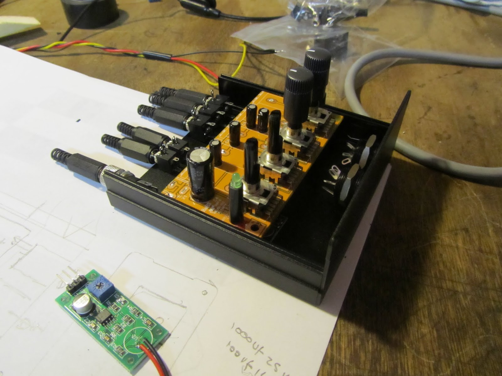
Part way through a little project - adding multiple headphone outputs and mic inputs to the existing FM Radio/SD card player system.

Motorcycle or Rally intercoms can all be bought off the shelf, for a price. 
I'm more interested in tinkering and dismantling/hacking/integrating a few existing components to see what I can come up with. Wireless is overrated IMO - just more things to charge up!

The Schematic

The principle is to leave the audio route from main Head Unit to speakers and rear headphone jack alone since that works well.

Dotted line is the new unit, double arrows stereo paths, single arrows mono paths.

Green boxes are off the shelf components hacked slightly and integrated, Red - switches, Yellow - built up components etc. Two Microphones will switch in via a relay which also mutes the head unit via push to talk switches. The Amplirider will mix in the Mic signal and can be powered by head unit or intercom box depending which is turned on.


The build

Must clean up the bench!
Mic Amps mocked up and tested, currently working out the layout for the case

Layout should work:
    Output stage is a modified Behringer HA400 Headphone amplifier,
    Input Mic Pre-amp boards from an unbranded Ebay source
    Buck/Boost Power supply to provide stable 12v, again Ebay

Biggest expected challenge to be potential ground loop issues and wind noise in the Microphones - can't be any worse than the current drive/passenger 'shouting at each other' mode of communication.

More detail to follow.

Update - This approach was not completed, I invested in a motorcycle intercom and went wireless instead!

Saturday, 23 January 2016

Castle of the Eagles - Austria - planning

Hopefully headed south again this year - at least starting to think about it; a run through Northern France/Germany/Austria to one of the locations used for the filming of a family favourite movie: Where Eagles Dare. An excuse to head for some mountain passes.


Assuming the car starts of course.
It's been languishing in the Garage virtually since Barcelona... come on weather - cheer up!

Sunday, 29 December 2013

Hood frame

Over the Christmas break I did a little work on the roof frame but forgot to blog - its not finished - and another pause before I go further.

The pivots either side are in place, spring side is locked in place and tensions the spring, the other end is free to rotate:

The roller does spin on its spring as required:

The theory being it can be moved into place while inside the car unfurling the roof as it goes:

All well and good - just still not decided on the windscreen mounting method...  the old sheet I was using as template material was not working - far too stretchy and not really letting me work out the shape of fabric required.

Still needs some more thought.

Update - discarded this idea, it's just too complicated and not really worth it compared with a simple surrey top or a more traditional roof frame. For now I'm sticking with a surrey top fastened to the windscreen frame and over the roll bar.

Friday, 12 July 2013

Debugging the digital speedo

Its Sunny !

The British summer turned up and the weather has been good for driving, so while there are over 800 miles on the clock now I've made no progress on the roof. 

Reminds me of an old cartoon in my favourite childhood book: Story Book Dictionary -now- Best Picture Dictionary Ever  by Richard Scarry

One of the Busy Town animals has a large hole in his roof:


Wow - just thought - theres my '80/20' rule or 'Good enough' lifestyle choice right there - learnt probably before I was 5 years old ha!


Digital Speedo Circuit Design

The circuit itself is cribbed from a number of forums existing projects etc & I found some great online tools for checking & drawing circuits:
  Circuit Lab allows full simulation over time & 30 day free trial
  Digikey Scheme It allows diagramming for free\

My current circuit intention is something like this:

S1,S2 - Front panel momentary select & reset buttons
R1,R2 - 5k6 pull-ups for the I2C bus
R3,R4 - 10k pull-downs on the switch inputs
R5,R6 - 200R current limiting on the 12v sensor inputs
D1,D2 - 5.1V voltage limiting Zener Diodes on the 12v sensor inputs

Mocked up currently looking like this:


+5v will be via a solid state regulator to drop me down from the car's 12v line

Inputs are 12v current and voltage protected with resistors & Zener diodes.

The illumination input will be to turn the brightness down rather than up - i.e. when instrument illumination is on its dark outside so I want to avoid glare from the LED display; not yet even mocked up.

The display is from ByVac and accepts an I2C/Serial input so I don't need a rats nest of wires/pull-ups to multiplex the 4x digits or continuously refresh it. In theory I2C bus can support multiple devices on its two wires so I could upgrade to a small LCD, Multiline or any I2C output device.

How long does debugging take...

Its been a while since I coded anything, its pretty good fun though;

I think I read somewhere (I could have the numbers completely wrong) you can write about 4 lines of bug free code a day - not through slow typing, just because debugging takes time. Arduino tools are pretty basic too, the debug cycle is to embed print statements in the code, download, run, monitor the serial output - no single stepping :/


Some progress though - the project has expanded & I now have basic menu code working for functions with two input buttons: select & reset. The functionality will be:
  • Speed - to 10ths of MPH
  • Selectable speed warnings at 30, 50 & 70 mph
  • Trip 1 & 2 - to 100ths & 10ths of a mile respectively
  • 0-60 timer - starts when the car starts moving or red button pushed
  • 1/4 mile timer - starts when the car starts moving or red button pushed
  • Calibration - on the fly tweak speed up/down & entry of pulses per mile - could even drive this via the USB/Serial input i.e. console base calibration.
  • Sense instrument illumination to adjust brightness

I'm trying to tidy up the timing code for measuring speed based on the time between bolts passing the speedo sensor but its been hit & miss without a proper function generator to test it. I have this rudimentary pulse generating code creating an output on one pin which I feed back into the sensor pin - hence that flying wire on the picture above taking the output back to the sensor input.

Unfortunately - up to a point - I am a perfectionist with code, keep tinkering, re-arranging, checking until it both works and looks pretty.


Update - the digital speedo is on hold until the dash next comes off and I add circuits - which wont be while the weather is so good!

Friday, 28 June 2013

Projects in progress - half hood & digital speedo

Half hood

I have a couple of projects progressing currently, the first a half hood - awning type cover. I'm going to give it a go myself. Materials are already ordered from Ebay some Cordura fabric & thread; Today I worked on a simple model of the windscreen & roll bar to start to identify the shape I want & start to get a feel for the cutting pattern:

Granted paper & fabric don't behave the same way - but it helps to visualise the situation. I have slightly different fixing points to the norm, I'm not going for a line of poppers along the front of the windscreen surround:

I've not really done any work with fabric before, so no guarantee this will work; I think the next step is a mock up with some old sheets to work out a cutting pattern:

Digital Speedo

My other project is a digital speedo. Nothing wrong with the Smiths clocks I have, but I'm used to a numeric speed readout to keep on the right side of speed cameras & average speed checks.

I confirmed with Smiths that the existing 'bolt detector' speed sensor can drive another unit, so I'm playing with an Arduino Nano board and LED 7 Segment display to see what I can come up with.

My display driver is written so I can display text & fixed point numerics, Frequency measuring code also written for frequencies around 3-300hz = 1-100mph down to 10ths accuracy & I have the basic sensor circuit in place to drop the 12v sensor signal to 5v. I could do with a frequency generator to fully test my code - so either I need some more code for the Arduino to generate a known frequency using a spare clock and output pin or or hook it up to the car and see how we go.

The trick, I suspect, will be adding the right level of averaging/damping in the code to get a stable/usable speed display:

There is lots of potential here for an accurate distance/trip meter, 0-60 acceleration clock, lap timer etc

All just work in progress so far.. just depends if my mood is debugging code or sewing as to which makes progress next.