Sunday 30 September 2012

Nearside Carpets & tunnel

Nearside tunnel carpets & seat back carpets fitted: (The floors will need a hoover at some point)

Making a start on the boot space carpets, the back carpet is not in yet - I want to finish the spare wheel holder & changes to the back panel before covering it:

The tunnel cover needed adjusting around the handbrake to accommodate the warning switch & the gear lever hole cutting out. The Type 9 gear lever is off centre, however I decided to go for a centred hole which will mostly be hidden anyway by a gaiter:

Once the carpet is fully dry I can trim the top edges level with the chassis tubes and make a decision on fastening the tunnel top - rivnuts in each side is a possibility.

Impossible P clips - brake lines

The brake lines now secured down each side of the engine bay with P clips. The two clips near the front of the car are nearly impossible to drill - even with a shortened drill bit (i.e. one I snapped by accident earlier) & 90 degree attachment, all the chassis tubes converge to leave very little space for working:

While the completed job looks fine, the holes for the frontmost clips didn't end up too pretty & the drill bit did spoil the powder coat as it wandered due to the angle I was drilling at. I used a little black hammerite to make good.

Nearside tunnel panel

I marked and drill out the mounting holes for the speed sender bracket, then riveted & bonded the nearside tunnel panel:

Waiting for the bond to go off then all the carpets can go in & the tunnel top.


Liquids

Time to put oil in the gearbox & diff, I had been putting this off - irrationally - I just had this feeling something would start leaking...

There's just enough room to get a stock funnel into the gearbox with panels on. My Type 9 took about 1.9 litres:

The Sierra 3.62 ratio diff took about 1 litre. Its also managing to leak/weap very slightly from one of the back plate bolts, so off to Machine Mart to pickup a T45 Torx bit to give it a tweak. I'm assuming/hoping it was the one loosened to original drain the oil (before it was in my ownership):

Not much to see...


Update +3 hours: I couldn't move the cover bolt in question & its not leaking anymore... I think I'll just keep an eye on it

Update +24 hours: no leak... perhaps the original was a splash from filling?

Update +5 days: no leak... result! it must have been a splash/drip from filling


Saturday 29 September 2012

Chassis loom - reversing light switch

The Type 9 gearbox reversing switch location leaves <1cm to the tunnel side. With hindsight I should have organised the loom/plug for it before the gearbox was installed:

The standard GBS loom comes with 2x spade connectors which are completely unsuitable. I took apart a couple of bullet connectors (Red Bullet Sockets from Maplin seem to be right), carefully bent the end at 90 degrees and covered with shrink tubing to make the appropriate connectors. Its still a fiddle to get these in place:

High Pressure Fuel Lines

Completing the high pressure fuel circuit:


It looks close to the clutch cable, but infact the fuel line cannot touch it - I'll probably double check before going to IVA.

Decided on routing around the outside of the plenum:


Note - I re worked this last line (Here) - the return from the pressure regulator to the swirl pot later in the build. Still going over the plenum, but then following the outside diagonal chassis tube on the other side of the steering column to give more clearance. 

Part way through I thought the lines might want to sit lower under the steering column, i.e. as they enter the engine bay drop right down to the bottom chassis rail. That is the route taken on the factory build cars - I'm still thinking about it...

Friday 28 September 2012

Clutch cable

GBS said its possible to notch the bellhousing to get a locking nut either side & hold the clutch cable in place. I decided to notch a nyloc instead; partly because its a lot easier to access than the bell housing for cutting & mostly because its more reversible - i.e. If I make a mistake I am only destroying a nut worth pence.

The M10 nyloc plainly can't be tightened as much as when it was whole - but its a good tight fit on the threaded rod:

The extra nut just helps hold the cable in place. Now there should be no chance of this end flexing when the pedal is not pressed & letting the end of the cable come out of the clutch release lever:

Update - while this works to anchor the end of the cable, its laborious to take off - unscrewing the lock nut from under the car along a couple of inches of fine thread.

Monday 24 September 2012

Accelerator pedal & cable

The accelerator pedal is to wide, so both ends of its pivot tube need cutting/grinding down. I used appropriate stainless & thick BZP washers to get everything mocked up. The clevis as supplied is too narrow to sit astride the pedal top & too wide for the clevis pin to sit on one side. I adjusted/bent it into a more useful shape:

Slight adjustment, bending, of the front of the pedal box cover so the cable takes a straight route from pedal into its tube. When moving the pedal it pulls at the front of the stainless pedal box, so this will definitely need rivnuts along the front edge when fitting the lid to keep everything rock solid: (That nyloc is not tight at this point - this will be dismantled before final assembly)

Final, belt and braces, a 2mm cable clamp just incase that screw type clamp comes lose:
The route, for now, appears to be along the outside chassis rails with potentially a fixing point on the top chassis rail & again on the diagonal to avoid any contact with the steering column - for now its just offered up:

Arrival at the air intake butterfly valve on the front of the plenum, simply clips into place. The cable adjuster/stop needed winding out considerably to ensure full throw of the valve is possible:


All mocked up and cable route identified - check
Final fitting will only be when the sides are in place.

Sunday 23 September 2012

Direction...

I'm at risk of starting too many jobs at the same time so going to plan a specific direction;

Target:


Get the side panels on, which in turn will allow fitting the firewall, scuttle etc
Before they go on I need to:

Interior areas preparation:

  1. Complete the chassis loom routing - working forwards from the boot space along the tunnel
  2. Install the spare wheel mounting bracket on the rear panel
  3. Complete the boot space carpets
  4. Complete the transmission tunnel & nearside footwell carpets 
(all the carpets together so the adhesive doesn't go off in the can after opening)

Engine bay preparation:

  1. Complete the engine loom routing - including IACV extra circuit
  2. Install the HP fuel circuit
  3. Install the water catch tank & washer bottle
  4. Install (or at least plan & route) control cables: Clutch & Accelerator

Earth straps and distracted into cooling system

Earth straps

A little wiring work to fix the rear loom grounding point to a rivnut, and start securing the remaining loom. I need to get under the car & offside rear wheel off to complete this though:

Then engine earth strap, which needed a custom short bolt into the engine block. Not pictured here I also changed the spade terminal for an eyelet on the starter solenoid loom:

Thermostat housing

While installing the engine earth strap I wanted to double check the space on the nearside engine mount plate for the cooling overflow bottle... got distracted and started assembling the thermostat housing which was in the same bag.

First up a blanking plug which has both a copper gasket and some instant gasket:

Then onto the adaptor plate in order: Gasket, metal ring plate:

Thermostat sits flush into the metal ring plate with another gasket on top. The thermostat is 95 degree operation (stock from GBS) & already has a bypass hole (bottom of picture) to provide some flow until it opens. I think I'm right in putting the bulk of the thermostat on the underside so it sits in the hot water from the engine jacket to open it at the appropriate temp:

Then the thermostat housing sits on top:

Update -  Reference Paul's build for some advice on cleaning the mating surface between the  water rail adaptor & thermostat housing. Reference my later re-assembly for the mating surface between the head and water rail adaptor

Update - Its worth making sure the cap seal surface on the casting is completely flat and makes a good air tight seal and the cap innards are tall enough so the pressure gasket makes a tight seal on the inner casting surface. Reference later remedial work on the cooling system

Saturday 22 September 2012

Boot floor

Finishing off the boot floor; The two end plates go in - only riveting where I know I am clear of the fuel tank & bonding around the entire perimeter. The second picture shows the large gap between the back of the fuel tank and the rear panel:

In passing I also thought through & circuit tested the potential need for a fuel tank earthing strap - The fuel sender is earthed via the loom and the sender electrically connected to the tank by its screws, I don't think it needs any other earthing (might check for consensus)

The fuel tank sits about 10mm under both the end plates and the general level of the boot. I'm using some foam carpet underlay to level off the space & in due course will be creating a simple fabric link between the floor and back panel to avoid things falling down the gap onto the road:

Flush fitting rivnuts installed to hold the differential area access plate & some rubber trim edging to stop the worst of the road water/dirt getting into the boot space:

The fuel sender has spade terminals, the loom comes with eyelets & with hindsight I should have done this before putting the rear panel on, bending over the boot area to solder/strip wires is not that comfy:

I used a couple of linen kitchen cloths tailored to fit the boot space to fill the gap between rear panel and boot floor. Simply cut to shape and corners/fraying edges held in place with rubber glue (Copydex):

Offered up, but not to be fixed until I have finalised the re-enforcing on the back panel for the spare. My intention is to glue these only to the back panel so I can lift if need be and gain access to the wiring, fuel sender etc. They will do the job though; there should be no issue with boot contents finding its way onto the road. This is all eventually covered with carpet: 

Chassis plate

My original chassis plate had to come off.
I thought I would save time and get one fitted before delivery of the kit, i.e. get the only piece of welding on the build out of the way - unfortunately a mistake meant it had the wrong VIN embossed.

I tried a number of options, including re-stamping the existing plate & stamping the chassis direct - ultimately though I needed my replacement VIN plate welded on.

RHOCaR helped out - specifically Jon (a.k.a. owlman) kindly offered to drive over and weld the new plate on for me. Many thanks Jon!

Jon drove over in his Robin Hood 2B, which not only woke the neighbours up :)  but also reminded me the sort of machine I'm building & added to my enthusiasm to get my Zero on the road. Jon's 2B:


My chassis plate - sorted:

I put the plate in the same place GBS put the original - it turns out (hindsight again) there is an oval opening on the offside panel lip to fit the plate under, it may even be possible to glue it in place under the side panel and appear as a permanent fixing avoiding the need for any welding on the build.

Friday 21 September 2012

Reversing & Fog Lamp install

I decided to go with rivnuts for the reversing & fog lamps, much easier to install/remove/adjust them than with the standard nuts & bolts that come with the lamps.

Extra care opening up the mounting holes to 9mm, the fuel tank is sitting about 20mm behind the rear panel. Then I used a scrap bolt and pliers to bend the rivnut to sit horizontal, rather than at the panel angle:

The lamps were already modified but I also had to sand down the posts that the bolts fit through so the casings would sit flat against the rear panel. The fog lamp must be aimed horizontally and not point upwards to pass IVA.

The only gotcha was the loom label on the offside cable, I should have removed it before feeding the cable through the hole/grommet, it needs to come off to feed enough cable through & was difficult with the rear panel in place.

Sunday 16 September 2012

Clutch cable - second try

My second attempt with the clutch cable. The bracket is now lined up square so the cable is in line as it emerges from the outer into the pedal box. I also decided to open up the slot in the pedal box and fit the large round grommet which comes with the cable:

The route under the plenum & in front of the engine mount isn't great though - I would really prefer to run it behind the engine mount (bottom of picture) but its not quite long enough:

Its really hard to see from other builds the best way to do this; its just not feeling quite right at the moment - left or right of the chassis tube, infront or around the engine mount...

The current cable is 36" long (inner) and 32" outer. A 37" cable would be perfect - if I can work out where to get one.

Consulting RHOCar & thinking on it...

Confirmed this routing is correct - just needs some cable ties to hold it in place.

There is also an option to notch the bell housing to allow the locking nuts to sit either side, I might do that in due course - alternatively - a cut through a nut would allow it to slip on the threaded end to the same effect.

Pedal box

A little change from the wiring, but also in the vein of creating fixed end points for things; I started to think about the firewall, and with it the the pedal box.

Firewall

The firewall sits flush with the chassis tube on the rear edge (I think - by deduction - unable to find other references), i.e. other side of this picture - I've marked out the drill points on the masking tape; but its waiting for M6 cap head bolts before I go further:

Next up was fitting the pedal box, as it stands all the folds on the box are somewhat open/large radius and it doesn't really line up. The accelerator pivot goes through one side so this - with the position of the firewall provides a datum for mounting.

Pedal Box Cover

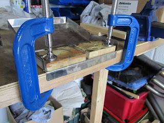
The pedal box cover needs bending in the middle. I don't have a metal bender so setup some scraps of wood, fixed everything in place with clamps & gradually pushed it into place by hand:

Next the top edge isn't bent at all; this needs a 90 degree bend which is achieved using some scraps of timber to hold it in place and more timber as a 'soft' lever to push it over followed by some light hammering to tighten the bend:


Pedal Box

The box itself sat to high as it was and would not let the accelerator pivot bolt slide into place. Taking care to line everything up & take account of the panels it will sit on, i.e. the box sits against the firewall & partly on the scuttle tray, I tightened up some of the bends. I used the fixed 'true' corner on my bench, clamped in place with scraps of wood then hammered over the bend with a claw hammer. I went along both edges to make sure the resulting corner (bottom to back edges) was still square:

This is the result, pedal box sitting in place with the accelerator bolt now able to sit squarely through the side hole into the chassis hole. I also cut out a recess bottom right so the box sits square around the clutch cable support:


Final check was to install the brake reservoir (a little brake fluid on the rubber grommets required to allow it to push fit into the master cylinder). The pedal box cover currently sits on the reservoir; when I drill the cover fixing bolts I'll make sure to give it a little clearance:

I also went around all the exposed edges with a small grind stone on the Dremel to remove the worst of the laser cut sharp edges.

I need to think through which parts of the scuttle & battery tray will be removable - it would be good to leave access to under the tray without leaving obvious long joints which will allow water/weather to get in.

Issues

1. I need some M6 x 20mm cap head bolts for the cover & firewall mounting; waiting on Screwfix until Tuesday (picked up 20th Sept)...

2. The accelerator pedal is far too wide to fit in the pedal box, its pivot tube is long by a 10mm at least, need to double check before cutting it, but presumably I can just cut it down to fit.

3. All these parts, pedal box, battery tray etc are located according to the notches in the side panels so nothing can be fixed at this point