Monday 30 July 2012

Gearbox bell housing & clutch release

I didn't want to try and fit the sump on a quick evening session, I don't want to be stuck part way through that job with the engine on a hoist & have to leave it overnight.

So on to a smaller job - I thought I would mark up the bell housing cut out & some little jobs on the gearbox assembly.

Pivot change

The GBS solution to getting the correct throw at the clutch release bearing is a change to the pivot point - the old one (smaller) is removed by tapping out from behind, then the new larger one tapped in - using my 'wooden dowel' drift and a hammer:


Clutch release bearing & arm

Unpacking the release bearing I ran into a problem - it looks like it has suffered in transit/packing. The broken edge doesn't look terminal, however this part is approx a £20 value & is engine out time if it completely fails. I'm going to have a chat with GBS, but think I am going to invest in a new one.

Rats!

Offered everything up to check the fit & new pivot position, then removed until I get the replacement release bearing:

Bell housing adjustment

I marked up the required change on the bell housing, I'm going to double check some other blogs before cutting - the second picture shows two alternative cut lines, the higher one starting at the point the bell housing changes from straight to conical:

References:
    Phil Howard's build
    RHOCaR topic
    RHOCaR topic #2
    RHOCar topic #3 + picture of starter mount change

From these references it looks like my line needs to be parallel to the bottom of the housing, rather than across the corner as I have it marked.


Then I thought: If the gearbox, for any reason, fell off the bench its going to fall on the car and break something permanently - so its now sitting on the floor.

The sump is sitting under the pink sheet to the right - clean and dust free. I really want to install that first before doing any cutting since aluminium dust/shavings will go everywhere when I cut into the housing.

Sunday 29 July 2012

Raceline sump preparation

I'm not quite ready to complete fitting of the low profile sump, I need to drain the engine of oil so need a 5 litre tray for that. However I could prepare & assemble the new Raceline  sump for fitting.

This wasn't a cheap component, but the only option unless I was prepared, or able, to cut & re-weld the OEM sump. Its a well made kit so certainly don't regret the investment.

First job was to clean everything & make sure there was no production swarf or other remnants left. As per instructions I sluiced through and washed out with warm soapy water. This did find a number of filings especially around the baffles and in the corners of the pan:

Fitting the oil pickup with its o-ring seals, finger filter & the sump gasket. They all just push into place, then the oil pickup has a securing bolt to the bottom of the pan. The gasket is keyed at either end and can only go in one way.

Everything was left to completely dry out from the cleaning at this point.

Two tiers of windage trays. Bolts, lock washers and Loctite on the first one, then standoffs (two of which are keyed) bolts and Loctite on the second. A little challenging to torque the 4x bolts on the curved part of the windage tray, I don't have any hex drive attachments for my socket spanner. They all have thread lock & tightened to 20nm.

Some more tools required before I can go further, 32mm socket so I can tighten the plug on the filter, a wide opening adjustable spanner (for various jobs) & a 5 litre+ oil tray for emptying the engine.

Friday 27 July 2012

Toss a coin..


A few reasonably challenging jobs come next:
  1. Sump replacement - dangling the engine on the hoist <- This first
  2. Rear panel fitting - first major panel bending
  3. Chassis/Engine loom adjustments - tease out wires for FIA switch & inertia switch

I'm not sure which one tackle next...

Turns out I didn't order the rear panel fixing kit - 4x button head bolts/nuts etc - that might be an excuse to wait for an Ebay order of same and do the sump first?

I don't have a large enough socket (or spanner) for the new sump drain plug & no large capacity oil tray to drain the engine - I can probably prep the Raceline sump kit though.

Spigot bearing

To run the engine lengthwise rather than transverse the crank end needs a small spigot/needle bearing inserted which the gearbox shaft rides in. You could probably just about get it into place without removing the clutch - but its easy enough to remove and re install.

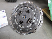
6x bolts on the clutch remove the housing and pressure plate:

The spigot bearing is inserted, rubber seal (top in this picture) facing outwards, to stop ingestion of debris/dust from the clutch.

It is carefully driven home with a hammer & drift (I have a 5cm long wooden dowel which did this perfectly):

I bought a clutch alignment tool which grabs hold of the clutch casing and clutch plate and keep them all central during mounting. Taking care to keep the clutch plate the same way round - it has a front &  back. 

Hindsight - I could probably have attached the tool before removing the housing to keep perfect alignment, its easy enough to line up the clutch plate by eye though.

6x bolts, they have splines on the heads to stop them shaking lose, torqued, alignment tool removed and all set:

The engine crank shaft actually rotated slightly whilst loosening/tightening the clutch housing - so good news anyway, its not seized since it was manufactured 8 years ago in Feb 2004! :)

Exchange thermostat housing

I'm using the GBS water rail, so the OEM thermostat housing comes off and is replaced. For now just the right angled tube itself incase its harder to get at once the engine is in the chassis. The thermostat housing bolts to this from above so I can leave that until later.

A little feature of the gasket, that top arc which should be around the top right mounting hole is actually cut to the left by a cm or so. Trimmed it with scissors after this picture:

3x hex head bolts supplied with the kit, loctite in place & holes taped. Spider ingestion is just as likely as dust in my garage:

Update -  Reference Paul's build for some advice on cleaning the mating surface between the  water rail adaptor & thermostat housing. Reference my later re-assembly for the mating surface between the head and water rail adaptor

Wednesday 25 July 2012

Remove exhaust manifold

Quick job on the engine this evening; remove the exhaust manifold & the heat shield behind the lift eye:

The 3x studs had nuts pinched onto them rather than locking, so undoing them took out the studs too:

Outlets covered to keep clean & gasket saved. The heat shield comes off to expose the mounting holes in the head for the water rail

Hindsight - Masking tape leaves a residue if left in place for more than a day or so & the residue is a real s*d to get off - the glue dissolves in white spirit, but the tape is waterproof meaning its hard to get to the glue!

Sunday 22 July 2012

Engine fuel rail

Now the manifold is in place I started to juggle the various parts that need to fit on this side; the fuel rail, fuel pressure regulator, feed pipe and injector loom.

I have seen other blogs which switch the regulator and feed pipe ends to bring the fuel inlets to the back of the engine rather than the front, so this seemed a good place to start:

There is an engine loom socket just behind the regulator which cannot be accessed when it is installed right way up, and when upside down the plug can be inserted but only just & needs the fuel rail removed to do so.

For now I flipped the pressure regulator upside down but will need some advice before making this permanent: (seems ok - see later in this entry)

Bending the fuel inlet pipe seemed easiest when one end was anchored on its mount, being very careful not to kink it and not put too much pressure on the braised ends. I also checked the injector loom would fit & offered the plenum (not pictured) to check clearances.

Still not sure what to do about the end of the pipe pointing straight up though.

Flipped it over and adjusted the route carefully to miss the plenum which bolts onto the inlet ports:

Now I have the fuel out and return at the back of the engine roughly where the swirl pot will be.

Outstanding issues to think on:

  1. Can I fit the standard regulator upside down?   Yes 
  2. The fuel inlet pipe end is now pointing straight up - I need to either:
    1. Bend it downwards 
    2. Cut it shorter
    3. See if the pipe would fit the other way up under the fuel rail without getting in the way of the plenum  <- This 
Example work found on S Bradley's blog: SJ Bradley blog - fuel rail


Hindsight:

I ended up re-working this for a couple of reasons:

  1. There was not enough room at the rear end of the engine for plenum vacuum outlet, engine loom & pressure regulator.
  2. Notwithstanding SJ Bradley's example - I think the plenum has changed design since
  3. I really didn't like that re-bent original fuel pipe - just looked too messy

Engine inlet manifold

I couldn't resist a little tinkering with the engine, its been sitting patiently at the back of the garage for two months with no work done yet.

Dollie

A while back I actually made a simple mobile dollie for the engine which meant I could easily wheel it about. Invaluable in getting it out of the way when dropping the car onto its wheels, and very useful now to be able to turn it around and access all sides.

The dollie consists some 1/4" chip board & 4x castor wheels screwed in the corners. Rough & ready but a must have tool!

Dismantle

I decided to remove the inlet manifold and re-fit the modified manifold ready for the GBS plenum

Removed, butterfly throttle valve, injectors and inlet gaskets carefully removed for reuse:

The old manifold stripped of components does not get used:

Assemble

With all these parts on the bench it made sense to re-assemble on the modified inlet manifold and back on the engine to keep everything clean. The modified inlet manifold comes as part of the kit, just needed cleaning and then the gaskets from the original carefully transferred over:

Then the fuel rail complete with injectors push fits back in and held in place with a couple of bolts, again off the original manifold:

Cleaned the head with a little white spirit on a rag to get rid of any masking tape residue:

Then the new modified manifold with fuel rail and injectors simply bolts back into place. This is not tightened up, the plenum will sit on the same bolts in due course, for now this just lets me work out the engine loom & fuel rail positions as well as keeping the injectors safely clean.

Low pressure fuel lines completed

The tank is bonded in solid, so just the last two lines from tank to fuel pump and the return to the tank & the low pressure fuel circuit is complete.

I had to file a little lead chamfer on the tank connections which would have been easier before I fitted it but no real issue.

I used the same approach I have seen on Dave Smeaton's build to hold the flexible lines in place, a long cable tie with some spare nylon pipe to hold in place but not restrict a little movement (the one pictured here is actually pulled tighter than this now)

Also double checked I left the jubilee clip heads in places I will be able to get to when the body is on.

Saturday 21 July 2012

Fuel Tank

Various jobs moving forward, it feels like a good next milestone is to complete the rear end, so:
  1. Install the fuel tank
  2. Complete the low pressure fuel circuit to the tank
  3. Install the rear panel (bottled this for a bit - played with the engine instead)
The fuel tank in place will also give me a fixed point to finalise routing of the rear loom.
Not least; If I fit the rear panel I can stop tripping over it where it sits along the side of the garage.

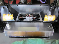
To that end, I took a look at the fuel tank, cleaned up the burrs on the inlet/outlet pipes & installed the fuel sender.

First checked the sender is working, showing resistance approx. 10-200 ohms across its range.
I also checked the throw on the sender float was appropriate & worked out the orientation to ensure it had free movement.

The sender is attached with 6 self tapping screws, I marked out and drilled 1mm 2mm pilot holes for them. I used duct tape inside the tank to catch any swarf, moving round with a new piece for each pair of holes. Even though the drill bit went through the tape, as expected, it caught much of the swarf on the way - so hopefully it worked ok:

After drilling I cleaned out the tank by sluicing through a little petrol to remove any obvious debris, cleaned up the tank and sender mating surfaces with a little white spirit and used a bead of Loctite 5922 around the edge and over the screw pilot holes to create a seal.

Hindsight - the pictures on KitSpares & other blogs show the sender unit with a rubber gasket - mine didn't have one - so I hope the Loctite will do the job!

Preparation on the chassis, a couple of stainless steel washers bonded off centre over the spare wheel mounting bracket holes to make sure any mistaken long bolt is unlikely to puncture the fuel tank immediately above. I also painted these with black hammerite reduce/eliminate the chance of any metal/metal reaction with the alloy tank:

I let the fuel sender and chassis washer paint go off all afternoon then proceeded with the tank bonding.

Couple of centre marks on the tank and chassis, & bonded in: a bead on the bottom 3 chassis rails & along the boot rail, then another bead/fillet on top once the tank is in place:

After these pictures I also marked either end of the tank on the chassis parts just above - a visual reminder when I fit the filler panels at either end not to drill down into the tank!

Once it all goes off over night I can connect up the fuel lines and route the loom.

Tuesday 17 July 2012

Loom first fit

The loom has been sitting on the bench all weekend, and avoided a little. Its a GBS standard loom, everything clearly labelled. I offered it up to the chassis today to understand the routing;

The fiddliest part is feeding it through above the diff into the rear space. The loom is reasonably thin at this point so my current thinking is to tuck it up under the fuel/brake lines and tie wrap it in place.

The fuse box is just roughly in situ, it ends up vertically on the firewall/scuttle back panel:

Rear end, all straightforward, I'll need the fuel tank in place to understand the best route from the diff area around the rear panel. Generally though, lots of loom, certainly not stingy or so tight to make the precise route critical.

The tightest part is at the back of the tunnel where brake line, hand brake cables & fuel lines all have to co-exist without touching. The loom should tuck under & attach to the corrugated wrap around the fuel lines at this point.

I might will run the loom under the fuel lines, to sit on the diff bolt spacer, just to the left of where it is now then loom & fuel lines can be cable tied to the spacer. The loom running to the back of the car is so thin & light it really doesn't warrant its own set of clips & will tuck away neatly under the other lines for most of the run.

I'm going to leave it sitting there for a while and think on it before anything gets permanent & need to dig out my circuit tester to find the fuel pump relay signal line & ignition lines to wire in my FIA switch & inertia switch.