Showing posts with label engine. Show all posts

Sunday, 31 May 2020

Loose ends

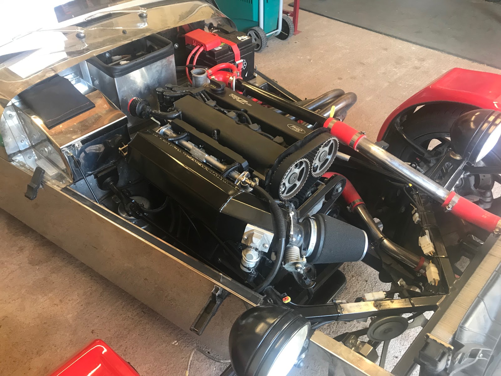
A few small changes to the cooling configuration and the final step in the engine rebuild to replace a dust cover.

1. Baffle to block the air gap between the radiator fan housing and the top of the radiator.


2. Coolant cap reduced from 20PSI to 16PSI

3. Reinstall the cam belt top cover which requires the aux belt and butterfly valve (or intake assembly) to be temporarily removed so it can slide into place from the front.

Subject to UK lockdown in Wales being relaxed, hopefully in the next month or so, we should be back to square one with a fully operational Zero!

A wash is all it needs now.

Monday, 25 May 2020

She lives!

So many parts to put back, rough sequence:

- Cam cover with new gasket
- Exhaust manifold with new gasket
- Thermostat to water rail housing with newly cut gasket
- Water temp gauge sensor
- ECU water temp sensor
- Water rail
- Plugs and HT leads
- Coil connector
- Oil breather

- Cam belt middle cover
- Alternator bracket and alternator
- Water pump pulley
- Aux belt tensioner bracket
- Aux belt

- Inlet/plenum arrangement with new gaskets to the head
- Air temp sensor
- Accelerator cable
- Throttle position sensor
- IACV cable
- Fuel rail and injectors
- Injector and cam sensor loom

- Various cable tie stand offs for all fuel lines.

- Refill coolant
- Coolant cap off to monitor bubbles
- Cam sprocket cover off to monitor cam belt tension after running

....all set...


Ignition - turnover - engine fires and runs.

Oil pressure comes up immediately.

Water temp rising slowly - at around 90ÂșC indicated (means nothing since the gauge is not calibrated) the fan comes on - and importantly goes off. Pre head gasket change the cooling system couldn't hold the temperature down so this is a good sign.

Coolant hoses staying flexible - no longer over pressurised from combustion gases.

No white smoke from the exhaust.
On turn off just a hiss from the cooling system - no spewing into the overflow bottle.

That will do for a first test! (video)
Some project.


RESULT - She's alive!


No guarantees yet - needs a road test once the CV19 lockdown is relaxed in Wales!


Addendum
All good disassembly/assembly projects should end up with a few extra parts - this one is entirely intentional. I couldn't remove it without cutting the connector off because of the alternator bracket. It isn't generally connected or used on a Zero/Emerald combination - although if it is a thermostat the emerald does support multiple temp inputs?

Not needed and no longer fitted.

Timing

Today is - camshafts back in, set timing, cam cover, alternator bracket and exhaust. 
That leaves only the intake side, fill up with coolant and see if it works again.

I didn't change the cam belt this time - its good for another 5 years & best part of 80k miles before it needs doing again.

This is not an instruction - merely notes/pictures - my guide is the Haynes manual - plus I've done this a couple of times before now. The process makes logical sense - Zetec cam sprockets are not keyed on the camshafts - they sit on a flat surface held in place only by their mushroom shaped bolts which allows infinite adjustment of position.


1. Crank vs. cam position

Timing pin sets the crankshaft position and this plate sits on the camshafts to hold them in the correct position vs the cylinders.

2. Crank vs. cam sprocket position

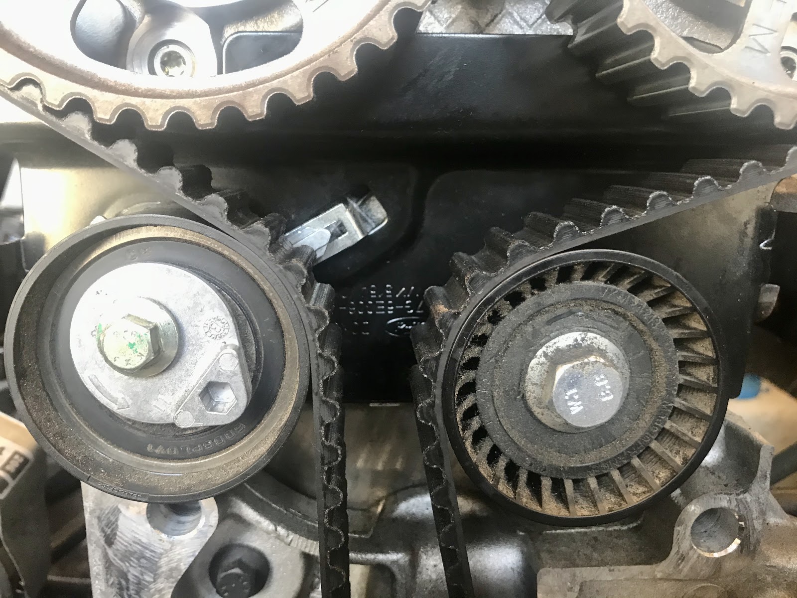
Timing belt is then tensioned with the left pulley adjusting until its arrow indicator is in the right place., sprockets are loose from the cam, this sets the cam sprockets relative to the  crank shaft.

3. Sprockets locked to camshafts

Then the cam sprockets are tightened locking them to the camshafts. The camshaft plate at the back is removed for tightening and replaced once done as a double check. The engine then turned by hand one cycle, two rotations and tensions/alignments double checked.

That should be it - timing set.

Sunday, 24 May 2020

Head on

Tools

Double checked my torque wrench was calibrated with a couple of known weights and created a couple of guidance dowels to help re-locate the head correctly first time.


More Cleaning

Perhaps some paranoia about clean bolt holes, merely following the Haynes manual procedure, ensuring there is no oil or muck at the blind holes to avoid any chance of cracking the block when tightening. Compressed air followed by a rag and visual inspection.

Perhaps now just putting off the big step...


Head on

Cylinders back a touch from TDC to avoid any risk of contact.
New gasket in place - double checking orientation with the picture of the old one - turns out it will only go on one way round anyway. 

Looks really nice compared to the old one!

...and slide the head back on, down the temporary dowels to locate smoothly on the block. With no picture since I had my hands full!

New head bolts then lightly oiled and fitted - 20Nm intermediate, 40Nm full torque then as pictured 90Âș smoothly for final tension  - all in the order as specified by Mr Haynes.

I couldn't wait to get the followers all back in place - so many of them - and all had to go back exactly where they came from. It felt like this on the face of it simplest step was just waiting for me to knock the box over or be disturbed mid job and lose track.

...and pause.

Leaning over the car is less than comfortable and I'm in no rush.
The next steps - cam shafts and timing - all need equal amounts of clear thinking to get right so now feels like a good logical point to take a break.

Thursday, 21 May 2020

Head cleanup and measure

Note - As with every part of this build - this is the first time I've done it - this is NOT a manual - its my record of what I did.

Is it flat... enough?

Haynes manual spec says: "Maximum permissible gasket surface distortion 0.1mm"
Acquired a straightedge with spec: "Tolerance below 0.03mm"
Feeler gauges: 0.04mm upwards.


Prep

While tools were on order research via a selection of youtube videos + read the Haynes manual for the engine and consult with some trusted sources.

Very light cleaning with light oil, soft softwood scraper, then isopropyl alcohol to remove any gasket residue and then inside the cylinder/valve area lubricated lightly with engine oil again and left to dry.

The gasket left behind random bits of its rubber coating which sort of peeled off in places. Some discolouration visible, but also the original machining marks visible which must be a good sign that its clean.

It feels smooth to the touch - which sounds like a daft measurement - but fingertips are incredibly sensitive to local distortion - better than sight anyway - useless for overall bend across the whole component though.

Measurement errors

Built in I have potential error of 0.03mm from the straightedge, therefore worst case the ruler could be making the head look flatter than it is by 0.03mm (if they both bend in the same direction - top scribble).

If the head bends the other way to the straightedge error then it would make things look worse  (bottom scribble) of course I can't tell which if either is happening.


Therefore to detect the worst case I need to measure 0.1-0.03 = 0.07mm flatness or better to be within spec head flatness. Take off some for errors in the measuring process and I went for a 0.05mm feeler.

Am I kidding myself - or - is that logical?


Measuring points the obvious long directions, but also diagonals and really any flat between any holes. This picture showing the sort of pattern I adopted, repeated across all cylinders/head bolt holes.

Measure method #1

Lay the straightedge on the block, attempt to slide the 0.05mm gauge underneath, checking all obvious flats and paths between openings.


Measure method #2

Lift either end of the straightedge by a known amount - 1 thickness printer paper - and using a feeler of the same thickness as the paper (or even more of the same paper) check for any differences - loose or tight spots. (Thanks for this concept Graham)

The advantage here is the thickness of feeler is no longer critical to the measurement. I can measure down to the 0.03mm straightedge tolerance with a paper thickness feeler. The gauge should make it under with that little 'grab' you would expect in all places/directions. The paper may depress during the process - but even that should get me a fail safe/better resolution.

Result

So far - all good - consistent, no low spots no high spots identified with either method.


Left it for a day or so and repeated to make sure its not just my wishful thinking that its flat and make sure I'm comfortable with this stage before making the re-assemble vs skim decision.

Friday, 15 May 2020

Head off

The head is coming off hopefully just to replace the gasket but that depends if everything is still within spec.

Why am I doing this

The failure I believe is due to overheat caused by a failing temp sensor and lack of fan cooling when the car was stationary. i.e. I believe I have identified the root cause before this attempted fix.

Disconnecting ancillaries

Step one is dismantling, the head is coming off but to release it there are a number of steps.

Intake side: Injection rail, cam position sensor, plenum - inc accelerator cable and air temp sensor, alternator brackets x2
Exhaust side: Water rail, exhaust manifold.

First look under the cam cover and some tale-tale white on the bolt tops - coolant in the oil, corroborates the CO2 detection kit so she definitely had to come apart.

Cam shafts and followers

Water pump pulley to release the cam belt cover and cam belt, cam shafts out..

Cam followers all labelled to go back in the same place.

Parts table and boxes to try and stay organised.

Head bolts, nothing particularly noteworthy - they're not going back in.

Head

The head lifts off - a surprisingly delicate component for a heavy block of aluminium - oil and coolant channels everywhere and the valves smaller than you might expect packed together in each cylinder. A really impressive piece of engineering - no less impressive that they were built in the tens of thousands to the same standard.

Block

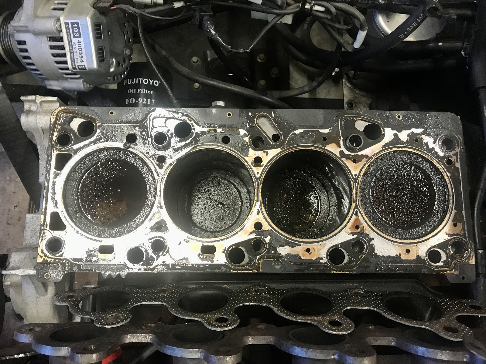
Cylinders carboned up after best part of 30k miles. Pictured with the old gasket in place and removed and liberal oil soak to clean.

First stage done.

It's all had a soak of WD40 and will sit overnight under a rag to help with cleaning and measuring up to see if everything is still flat. The operational spec on the head is max out of flat by 0.1mm!

The bigger challenge is can I put it back together and get it operational?
Worst case this will become an engine rebuild job for an engineering firm.


Update - Received knowledge (thank you) - WD40 is less than ideal for this job - it cleans, but it also strips any other lubricant or surface coating which can induce surface rust. I've since cleaned up and made sure the parts that matter have an engine oil soak/coating to ensure lubrication is maintained.

Saturday, 9 May 2020

It's not quite over yet...

Monthly engine turn over and warm yesterday - usual routine while the car isn't running to get the oil circulating etc. All looked ok, heated up mighty quick though and the fan was staying on - struggling to keep the temp under control - all at tick-over.

Thought I'd give it another go this afternoon - checked the coolant level and it took a litre or so top up hmmm...

Checked the coolant for CO2 and bingo -  blue to green...
...combustion gases in the coolant.

Plugs all look clean:

Dipstick looks good - golden oil, filler cap maybe a sign of milkiness - but could be condensation:

Compression test looks nominal getting on for 175 PSI - no particular low cylinder, I don't have the equipment to do a leak down test.

Quick chat on the Facebook enthusiasts group to get another pair of eyes/sets of brains/experience... advice is to check if the coolant system will still hold pressure if not and especially if it leaks into the cylinders then QED.

Theory - The temp sensor failure causing overheat in UK traffic on the way back from Norway pushed the head gasket over the edge. The car made it home - partly due to less traffic and a freezing night. I'm going with the temp sensor root cause, which is now corrected, unless I find any other evidence.

Broken out the Haynes manual for some reading...

Something new to learn, parts to find and order.

Sunday, 14 April 2019

Check for the missing valve collet

All procedures followed as per the Haynes Ford Focus manual - this entry is not an instruction,  I'm not listing all the steps or any of the torques, it's merely a record of the procedure.

Process driving after finding a valve collet in the oil pump intake filter, I need to know where it came from.


Dismantle

Plugs removed and checked, they all look clean to me, no discolouration on the insulators, no damage on the electrodes.

First step - engine to #1 cylinder TDC with a rod sitting in spark plug #1 hole as a visual reference to the piston position.

The bearing caps are numbered, I penned in same to make things more obvious, they have to go back in the same place and orientation.

Bearing caps loosened in sequence and removed,


Belt and braces parts laid out as they were removed and labeled Intake/Exhaust/Front etc,

Check the lifters

Looking for a missing collet at the top of the valve stems, the lifters pull out easily with a suction cup.

I checked all 16 but nothing a miss - the collets just visible between the spring cap and the end of the valve shaft at the bottom of each well. 

Good news then! at least I don't have to struggle removing / re-installing valve springs, just need to put it all back together.

The head casting looks rough around the end oil galleries, its the same on all of them so I guess just 'good enough', theres no swarf coming out in oil changes so its not degrading in any way.

Re-assembly

Crank back 90Âș so the pistons are all clear of the valves, then camshafts placed in and torqued down in stages and in order as per the Haynes manual procedure. The front caps also have sealant around the front edges.

Bearing faces oiled before assembly and all bolts wiped down to ensure no oil on the threads.
Both camshaft oil seals and the cam cover seal replaced at the same time.


Valve timing

I've been here before, just takes concentration to avoid doing something daft or missing a step.

Camshafts sitting the same way up as on disassembly and the locking bar slid in from behind,

Crank locking pin installed in the block and the crank gently turned to sit against it,


Timing belt over the pulleys which are then tightened to lock them in place and finally the tension roller adjusted so its built in indicator arrow lines up with the slot at the back.

As per procedure, remove the timing lock bar and pin then carefully turn the engine via the crank pulley 2x revolutions and double checked/adjusted the belt tension.

Then the sundries:
  Plugs, HT leads, Aux belt, Aux tensioner, nose back on, indicators reconnected.


Done!

On one hand a waste of energy dismantling the top of the engine just to reassembly it. 
On the other I had no choice but to check! 

It would appear someone dropped the collet during the engine build at Ford's Bridgend plant in Wales sometime in 2004.


Took RL13 for a test drive, everything running as it should.


Next job - number place lights have blown and MOT required there's always something :)