Showing posts with label ecu. Show all posts

Sunday, 15 April 2018

AFR Corrections - 1% of 21 is less than one

Penny drops.

My previous MO had been to periodically review the AFR Corrections values - % applied to injection, and apply those en-mass to the injection map. Especially when I'd been tinkering with some part of the map, axis ranges etc and getting more corrections.

But

The injection map has values ranging from ~20 - ~170, whole numbers with a maximum of 255. One byte, 8 bits per value.

If I apply a typical two decimal place -1.05% or +0.76% AFR adjustment to an injection cell containing ~20 even ~30 then the net effect is no change. My AFR adjustment is zero'd and effectively ignored. I've been discarding the bulk of fine adjustments every time I apply AFR corrections!

My guess is the Emerald ECU internally is multiplying the Injection table value by the MSPB value into say a higher precision 16 bit floating or fixed point result, then applying any AFR and other Adjustments as percentages to that before scaling to the ECU clock or interrupt frequency to fire the injectors.

So

New procedure will be:
   1. Review the AFR adjustments: apply and zero anything larger than + or - ~2.5%, 
   2. Leave anything smaller on the AFR adjustments table,
   3. Periodically run the result through the smoothing spreadsheet masking off any cells with an AFR adjustment.

If that procedure written in the manual somewhere and I missed it - just shows sometimes I need to learn the hard way! In this example, after a test drive through Kent, Green boxes showing areas to apply, red those to leave on the corrections table.


I do want to apply the large AFR adjustments - once they hit the current max +-15% threshold, applying them to the injection table will allow the Wideband to keep honing the map on the next cycle.

MSPB Milliseconds per bit

I scaled the entire Injection map using additional maps->injection scaling for a maximum 255. My map has some low rpm anti stall peaks which are always going to be the highest point so they may as well be 255 and increase the available bit range for other cells.

This automatically re-calculated my MSPB to 70ms from the default 100ms giving me a little more fine grained adjustment on the low TPS position cells i.e. minimum adjustment of 1 part in ~30 rather than 1 in ~20. 

The ECU is fascinating, especially when I get a little understanding born out in real world experiment.

Sunday, 8 April 2018

Injection table smoothing

My Wideband automatically adjusts the injection table based on the mixture sniffed from the exhaust. 

In an ideal world I'd run all combinations of Throttle position (TPS) vs. Revs to completely map the engine - exactly what a rolling road does - in real world road driving you get specific feedback points here and there peaks and troughs of mixture adjustment.

So, a little desktop work with a spreadsheet - the intention being to take the injection map as an input, apply a smoothing algorithm without being too destructive and produce the next iteration of the injection map.

Parameters

My spreadsheet implements a simple algorithm taking into account each injection cell's neighbours/adjacent cells. Its just averaging each TPS/RPM point to be somewhere in the middle of its neighbours.

The smoothing mask then applies those changes to the existing injection map while letting me mask out areas like low RPM/Stall catching which I don't want to change and the 2x areas of Idle and Fast idle tested during MOTs which I manage completely manually.

I'm also reducing the smoothing around the edges to help maintain the overall shape of the map.

The neighbour weighting table represents how much each adjacent cell affects the average - I'm setup to smooth more in the direction of acceleration - i.e. diagonally from low TPS/RPM (top left) to high TPS/RPM (bottom right).

Smoothing applied drives all the values in the smoothing mask - so I adjust influence over the entire table until the graph starts to look more progressive before it erodes too much detail - 75% seems like the sweet spot on this cycle.

The slowest step is copying out the current ECU injection map to the spreadsheet - the only way is manual copying.

Top left - current map, Top right - showing weighted differences to neighbours,
Bottom left - the smoothed map, Bottom right - weighted differences on the output.

This example from a second cycle of smoothing so only subtle changes evident - what should be happening is the bottom right differences are overall less than the top right.

Results

The output is a new injection map, table of changes, and a graph of the new map so I can immediately see if it looks right. I can then tweak the various controls to the amount of smoothing I need. Initial results look and drive well though, I'll give it a few more goes -  drive, add in Wideband feedback, smooth, repeat.

This table showing relative changes, ready to update the ECU map.
Example of the ECU injection map - with just wideband feedback, and then smoothed.

An iterative process - the primary driver on injection is feedback from the Wideband lambda setup, the initial results look good though - a good balance between point adjustments being implemented, smoothed into the map while maintaining the main features.

The smoothing IS destructive - its like weather eroding mountains and filling rivers, but it does seem to counter/help with the issue of limited feedback data points after driving.


Took the car for a drive afterwards - a good 100 miles around Sussex, she still flys and generated another round of Wideband feedback.

...and keep in mind,  I'm just an amateur tweaking/playing, some reading reference, doing what seems reasonable, but certainly nowhere near the kind of knowledge a tuner would have.

Friday, 6 April 2018

Accelerator pedal depressor - on the cheap

Time to prepare for this year's MOT at the end of May.

Requirements

I'm happy with the map - but its reasonably new due to the power change re-works and less than perfect battery compensation table. I have to hit the following criteria.

Idle is easy - foot off the accelerator - just tweak the few cells around 1k revs until its in the zone where the wideband can lock it onto the desired fuel ratio.

Fast idle harder - tested anywhere between 2,500 and 3,000 rpm - and requires an extra pair of hands/static right foot to hold the revs rock steady while I adjust the map. Turns out pedal depressors cost on the order of £40 - so thats not happening.

Extra foot

This evening's 7 minute task:
   Some fibreglass poles I'd bought for the roof and never used,
   A block of wood with an 8mm hole,
   A clamp.

Perfect - the wood becomes my third foot...

...the top of the pole clamped to the wheel holding the revs completely static while I play with the injection and AFR maps.

Total cost 7 minutes time and £0 for materials.

Monday, 2 April 2018

ECU Battery comp, Lambda and Cold start

Successful ECU tweaking session this morning, major changes listed.

All results documented on the ECU page

Battery compensation

The changes to the power distribution gained me a good 0.5-1.5volts which in turn threw the mixture off, slow idle lost etc. The culprit I believe to be an over eager battery voltage compensation table which was still on default values.

The steepness of this curve was noticably changing the mixture as the idle hovered between generating 13.2 and 14volts, 0.3ms doesn't sound like much but its somewhere on the order of 10% of the total injector duty cycle. I levelled the area betwen 12-14 volts and changed the overall shape.

A new avenue of learning opens up - the curve is directly related to the injector performance and should be documented against each type so my next task is to track down the stock battery compensation curve on a Bosch 0-280-155-820 injector!

Lambda

Some fine adjustment on correction gain and update frequency minimised the overshoot on lambda corrections letting it lock on at slow and fast idle. This was trial and error adjusting gain and frequency independently, slowly, to find the sweet spot of response vs. overshoot. I also checked the calibration on the Spartan2 while I was there - all still spot on.

Raised the coolant temp above setting so it doesn't fight with the cold start injection adjustments.


I smoothed out the areas around the MOT pass points and adjusted to closed loop, I dont want the ECU automatically/permanently adjusting mixture in the idle zone. Fast idle on adaptive until I've done some miles and it learns.

Cold start

Revisited cold start, the curve is the right shape, I just shifted it to last longer by changing the engine turns against each row. She starts without any throttle now ~7-10º ambient air temperature.

The curve stays higher longer for the first 120 turns, same as holding a manual choke out for around 8-10 seconds.

...and a new blue temperature driven adjustment keeps the mixture relatively rich until the engine is warm.


Start is good, slow idle is rock solid, just need some more driving to train the map.

Update - 6th April - tweaked battery curve and the target AFRs, needs a run now for everything to settle in.

Sunday, 1 April 2018

First run of 2018

Finally

    Snow x2 in Feb - check
    Week of stair-rods rain - check
    Re-assembled the car after modifications - check
    Even gave it a wash - check

16 mile round the block test - Yes - back in the groove!
A few waves from families out for their Easter Sunday walks - you don't have to be driving these cars to enjoy them.

All running fine when moving.

ECU

Adjusted various ECU settings (to follow) on cold start, and had to reset the area around idle which seemed to have leaned itself off too much. I still suspect the improvement in running voltage - a nominal 14.5 volts now has shifted to a different area on the battery compensation table and thrown things off.

Still a hunting slow idle to sort, but everything is basically working.

Sunday, 29 January 2017

ECU - AFR Targets and Cold Start

Finally the weather warming up to around 8ºC.
~10ºC is my rule of thumb for when driving the Zero becomes fun rather than asking for frozen hands/ears, in the garage I no longer get instant frozen fingers from picking up any metal tools.

A little tinkering with ECU settings.

An employee of Emerald who is active on the GBS Zero Facebook pages has been incredibly helpful with advice and some new settings to try. I also ran another round of cold-start adjustment. 

The current settings are listed in full on the ECU page, broadly the following has changed:
  • Some Emerald expert magic in the ignition and injection tables
  • Semi sequential injection enabled - so fuelling timed closer to when inlets are actually open
  • 850rpm idle column added in all tables - to help stabilise idle
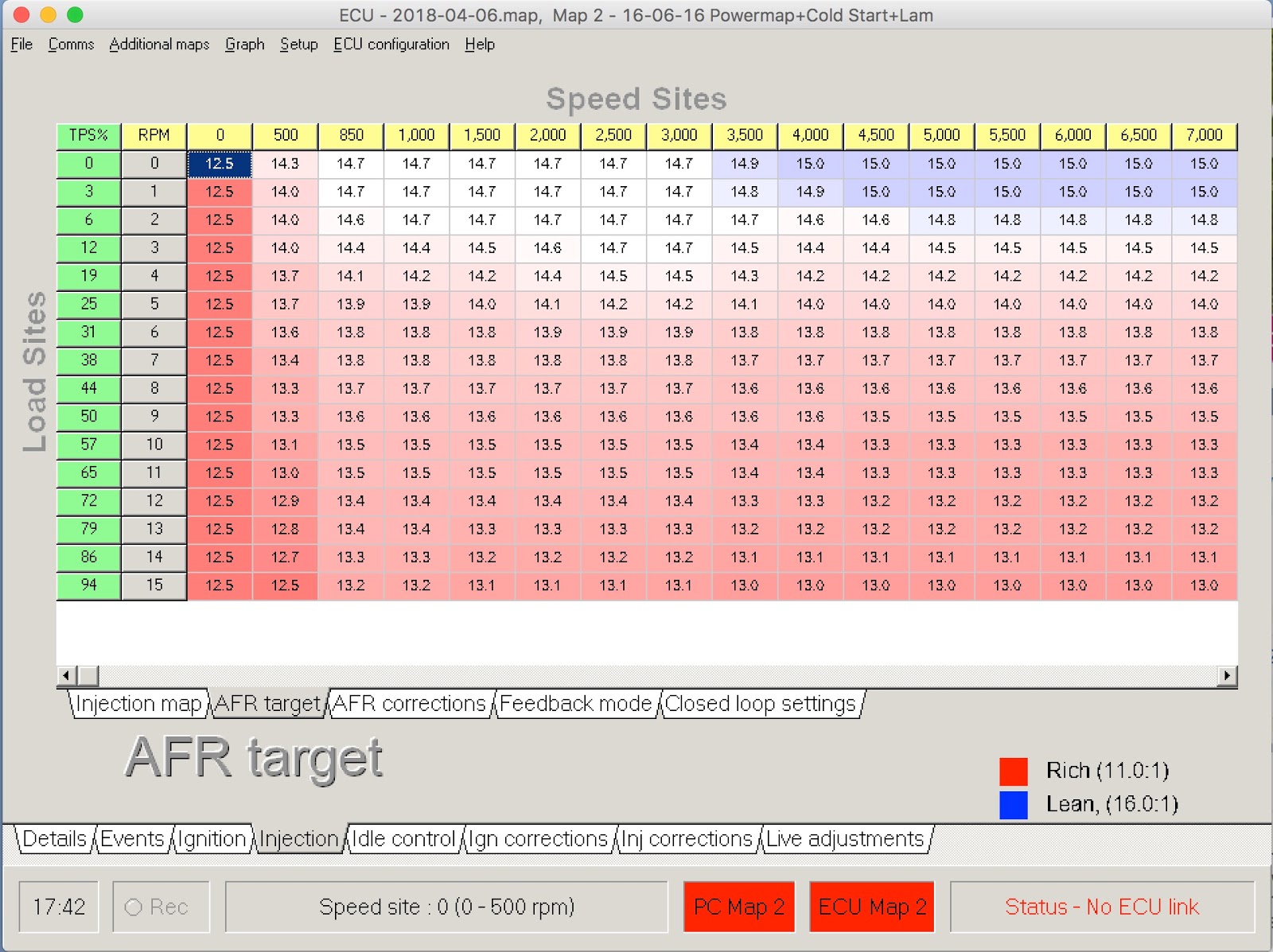
  • AFR Target table adjusted for leaner run in the idle/cruising area
  • Lambda settings modified
  • Cold start settings modified (again)

My primary map has the new flat/economy AFR targets on less than 30% throttle, secondary map remains on the power-map targets,  both still in adaptive for now to let it learn appropriate fuelling.


Target this year is to take the car through MOT early March, so I sync the annual test around summer driving months rather than having to cross that bridge mid season each year.

Starting to think about road trips... couple of ideas on the cards.

Sunday, 20 November 2016

Wideband Lambda - 14Point7 Spartan2

Time to upgrade the old narrowband sensor with wideband. This is partly due to continued challenges getting emissions correct for MOT, partly because its something new to play with, and significantly because I was made aware of a wideband setup with an in-build calibration mode to null out some variables caused by the install.

I'm chasing the holy grail of calibrated emissions using home/garage equipment without a full blown rolling road remap.

Installation

I'm using a Spartan2 setup from 14Point7 supplied by ExtraEfi.

I don't need a dashboard indicator - so went for the simple sealed unit.
The processing box was installed in the engine bay next to the gearbox - which should be reasonably protected from both the road and away from the hottest parts of the engine bay.

The sensor must not be detached from its cable or plug - due to built in calibration - meaning a hole in the car side panel large enough for the whole sensor to pass through. A small marine clamshell covers the hole, riveted in place for simplicity - if I ever need to replace the sensor its easy enough to drill out the rivets.


Wiring

The unit has simple wiring requirements - 12v, Main and Signal Grounds, optional LED output and a couple of Lambda outputs for wideband and simulated narrowband. Sensor ground and wideband feeding into the Emerald on pins 30 and 34 currently. Best advice from Emerald is use pin 10 as the input - however its working fine on 34 so I'm not changing just yet.
I wired in another circuit for it through the main fusebox to avoid having a trailing inline fuse on the loom, while everything was open I unsheathed and re-bound this part of the loom.

The Spartan2 takes its power from the ECU relay via its own 5 Amp fuse so starts up and shuts down when the ECU does.

Calibration

The interesting part of the Spartan2 is the calibration mode.
As soon as the wide-band module starts up it sends 2x known voltages/AFR readings, 5 seconds each, to the ECU. 

This permits correction for linear shifts and angle of the AFR graph, not the shape of the graph, but should factor out differences/voltage drops in installation wiring and even differences in Emerald's voltage measurement.

14Point7 supplies a spreadsheet which converts the calibration AFR outputs to two corrected points which can be input to Megasquirt ECU.

Emerald has a single decimal place on AFR, but shows and allows entry up to 3 places on voltage - so I re-worked the OEM spreadsheet to input voltages and calculate voltages from known AFR values.

Entering the calibration readings in volts, 1.642 and 3.314, in the top green boxes and the desired AFR points the sheet works out the voltages which correspond exactly to those AFR values.

Emerald does not allow selection of every voltage so the error column works out the potential error due to data entry - negligible and well inside the wide-band units accuracy.

.. Just needs copying in to the ECU settings and job's a goodun.
I suspect the wide-band has enough damping built in - so reduced the emerald signal smoothing to 0.

Gotcha - the only issue I found was by the time the ECU had powered up and connected to my laptop the wide-band had already gone through its calibration steps. The resolution was to power everything up with the wide-band fuse out, open the right Emerald Lambda screen then plug in the wide-band fuse, only needs doing once to calibrate.

Minor tweaking to restore the original powermap target AFR, and adjust the closed loop gain to get a stable idle. The idle zone used to have a lower AFR on the 500 revs column - meaning, as the ECU interpolates, its getting mixed messages - I flattened that out to 14.7 to try and give it an easier time of finding a stable tick over.

The only way to prove this is correct is a garage/MOT testing equipment - but it should be getting close & now have the controls to find the right emissions settings and have the ECU reproduce them using active feedback. I'm planning to try with a friendly garage pre MOT (next June) and if that fails a rolling road.

Monday, 29 August 2016

15k miles & 7k rpm

Out for a bit of a run today, left her in 2nd a little too long and found out the ECU rev limiter is working fine! A puff of white smoke from the exhaust and no more power as the engine saves itself from over revving.

Once home the ECU memory feature indicates the 7,000 max revs from its previous run.
I suppose thats one way to know the tachometer is correctly calibrated!


Milestone 15,001 miles on the clock now.


The red tape pointers on the speedo are typical continental European speeds 50, 90 & 120kph, to save me trying to read the tiny kph font on the clock when driving.

The digit decals on my smiths clocks lifting from their black backgrounds after too much hot weather running over the years.

Update - re revs, looks like no harm done, subsequent 80mile run shows no problems and everything running as normal, I guess put it down to driver error, thinking about installing an in my face shift light...

Sunday, 3 July 2016

Adaptive feedback update

Approx 1,500 miles on the clock now since shifting to fully adaptive.

I get a larger spread of feedback adjustments and the start of some changes in the higher rev range - car doesn't stay there for long on normal driving though so not yet a smooth graph.

0-500 rev range is excluded from the feedback process.

There is the expected top-left to bottom-right diagonal of feedbacks - consistent with relatively flat running and smooth acceleration in high gear, and the top row of values at zero throttle when lifting off and coasting. Not many hills on the Berlin run so only a little feedback on the left vertical - high throttle/low revs.


The original powermap high inputs at low revs are not great, I presume they are to stop the engine stalling, the car tends to bog down at low revs when pulling away and I suspect it's moving into this area. I may let adaptive adjust the 500 column in around 10% throttle and see if that helps.

Sunday, 19 June 2016

Adaptive feedback tests

More tinkering with the ECU settings.

I decided to let the narrowband re-map the power map dynamically.
I can always instantly switch back to the base map if required - in the meantime the experiment is to see if the ECU can work out for itself the correct fuelling to hit the 14.7 AFR.

This will obviously optimise for mixture rather than power


Test run today of about 60 miles showing the adjustments, percentages +- which are recorded, remembered  and applied over the base injection map automatically by the ECU. Mostly country roads some village drive at 30, some coasting behind traffic, some more spirited 60 mph - so a reasonable sample (sans motorway driving)

Looks like I was rich at idle and lean in that middling acceleration area.

The following graphs showing before (top) and after (bottom)
Left-Right is RPM, Bottom-Top is fueling, Front-Back throttle position.

The graph shape showing some reduction in fuelling at idle speed, but also small changes across the board, but nothing upsetting the overall injection map shape.

I'll leave it on this mode some more and take another look after a longer period.

Monday, 13 June 2016

Map Selection Installed

My MapV2 circuit now installed.

Obviously wasn't as simple as planned - I decided the map switch should be on the drivers side of the Aux panel in the space the old electric aerial override was. I also had to re-find the map lead from the ECU and as a consequence  tidy the loom arrangement behind, this short post condenses a good afternoon's work into a few pictures.

Meant stripping down the aux panel  to metal and re-assembling & covering.

Looks the part though - nice simple to-ground circuit with the guarded switch giving me clear indication whether I am on the primary/default map or secondary, closing the guard also forces the switch into the off position.

Saturday, 4 June 2016

Lambda and Cold Start

A little work on the cold start and various other ECU settings.
The car has always needed a little blip on the accelerator just after starting to keep it running, finally go around to playing with the cold start settings and resolving that.

I'm going to get it re-mapped at some point fully. in the interim the following improves idle and cold start.

The ECU Page is updated with current settings.

Areas of note

Lambda

The Lambda input is now setup so it doesn't just run against its +-10% stops all the time - it actually tweaks fueling according to the sensor input. Combination of:
  • Stock Emerald settings on the lambda curve
  • Tweaking the lambda gain control & update frequency to avoid overshooting fuelling


Cold Start

Larger initial prime leaving the enrichment on for 15 turns and some across the board tweaks for the higher water temperature re-starts.

Full setup so Emissions tests are easier is pending a full re-tune, theres just no way to do it myself without exhaust gas measuring equipment.

Sunday, 29 May 2016

Map Selection v2

Just some thinking through today and preparation for a full engine/ECU map.
I have a spare circuit from the immobiliser, so decided to use that in map selection.

The immobiliser will select a non-running ECU map to prevent the engine starting (along with the other circuits it breaks) by taking the map selection line to open circuit.

A simple single pole single throw map switch on the Aux panel will allow selection between the remaining two maps. When open the dash switch selects the primary map so if the switch fails still normal operation, if the immobiliser fails I can't start the car anyway.
Can't see its a security risk even publishing this. 

The wannabe hot-wire enthusiast would have to find the ECU map select input line or immobiliser wiring. Fiddling with the dash mounted map selector will not help other than possibly following the wire to the immobiliser.

If someone is really going for the ECU or immobiliser wiring to hot wire the car they would be better served simply picking up the car and towing it, or a dashboard off scenario to re-wire, or potentially re-configure the ECU to ignore map switching - hopefully that doesn't sound like a joyrider mindset. (Famous last words)

( + Its mainly me and my Dad that reads this blog anyway )

UpdateInstalled here

Monday, 8 February 2016

Map Switch

The car ran on an alternate map for IVA and with the first MOT approaching in the summer I got around to building an ECU map selection switch. This is meant for temporary installation - plugging into the Aux input socket on the ECU.

Design

The circuit designed to switch between the 3 possible Maps supported by the Emerald ECU. The second pole of the switch set to illuminate a LED confirmation of position.

The LED is setup to always illuminate Green, then also illuminate Blue or Red depending on the map selected - in theory this gives Orange and Turquoise. I installed a POT to allow dimming of the green to adjust the colour mix, in the end the POT probably wasn't necessary - the Blue and Red components are so strong they drown out the green anyway.

Wiring

ECU line #7b is configured as Map switch input - either open, grounded or grounded via a 1k Ohm resistor
ECU line #1 is the ground input
ECU line #8 & 9 are used to power the very low current LED draw

#8 & #9 are input pins with internal 1k pullups to 5v. I checked with Karl at Emerald and he suggested tying both together and using as outputs - it works, there is just enough current to drive the LED which only needs about 7-8ma when two colours are lit.


Assembly

Assembled in a small project box, possibly too small...

Connected via IDC cable to a right angled 9 pin D-Sub plug so it doesn't encroach into the passenger footwell.

Testing

 ...and in one possible location, just testing the configuration for now

Switch position 'O' gives green and selects Map 3, same as unplugging the unit:


Position 'I' gives blue and selects Map 1:

Position 'II' gives red and selects Map 2:

Next step is fiddling with the ECU setup itself to read the map selector from input #7b and copy in my 3 intended maps.

Half thinking about putting a VW logo on it ;)...

Update - This little box doesn't get used, I replaced the map switch with a more permanent install here and here