Monday 31 December 2012

Electrics - on and working!

Ignition switch connector

Once the ignition switch was re-wired the car could, in theory, be started - or at least the electrics turned on and some basic tests carried out:

The spare pink is for an optional remote start button which I am not using; everything else wired across according to the GBS instruction sheet. I write on the sockets too as a belt & braces double check:

Chassis loom routing

Then some tidying up of the front wiring loom; I wanted to at least get to the horn & test it:

This looks simple but took ages to route everything neatly. The front chassis loom has been languishing for weeks now not being properly fixed, its good to finally be in a position to connect it up:

Stock GBS horn, seems loud enough to me;

Power on testing

Then it was time for a couple of tests;

Before I connected the battery I just tested the resistance across the car loom battery connectors to make sure there were no short circuits - checked out fine - infinite resistance so at least things shouldn't go bang.
  1. Battery connected,
  2. Ignition on,
  3. Clocks all flicked over & back; Speedo showing 0000 miles, Revs showing oil warning (its not connected or filled yet), Battery warning & indicator tel-tales when the hazzards selected
  4. Fuel pump ran ( I didn't leave it running for more than a couple of seconds since theres not much fuel in the tank currently)
  5. ECU running
  6. Horn works ! :)
Its not an exhaustive test but very positive non the less, Very happy, first life in the car!

I think the next up test will be with more fuel in the tank & let the system pump through & prime the swirl pot/check for leaks etc.

(Disconnected battery live for safety)

Heater (again :)

More fiddling with the heater. I wasn't really happy with the bottom hose 45º connector so decided to try something different & hopefully simpler and more reliable before filling the system with coolant.

I'm going with the 5/8" pipe to keep things simple. The bottom edge of the heater is going to be mounted a little further out than the top so it inclines in the right direction for the bottom hose:

I'm using a direct 1/4" BSPT to 5/8" hose tail adaptor on the bottom pipe. The adaptor is much longer than the standard T7 hose tails so I'm hoping it gives the bottom pipe enough support; Its also too tight to get a jubilee clip in - although the only way I have been able to get pipes off that hose tail is to cut them off so again - hopefully we are good!

All back in place, I hope for the last time!
At least I'm getting some practice in removing/installing it; note also added the jubilee clips on the air hoses:

Saturday 29 December 2012

Front Indicators

My reading of the IVA (October 2012) is indicators must be:
  1. Less than 400mm from the widest part of the car
  2. At least 500mm apart
  3. 350mm to 1500mm from the ground
  4. 80º outwards, 20º inwards visibility
  5. 15º upwards, 5º downwards visibility
Checking various build pictures it looks like they roughly sit mid height of the front grile opening and roughly level with the front of the mudguards.

Measuring stick prepared with the key 350mm & 400mm measurements and begin to markup. I decided on 400mm height. The only weight not in the car is passengers and coolant, so I'm hoping this is a good margin above the 350mm regulation:

Double checked the steering on full lock with the mudguard roughly in place to ensure I have sufficient clearance:


Then the holes, 4mm pilots followed by 10mm x2. I decided to drill them on the car with it sitting level; the holes are just in front of the radiator position so managed to miss holing that too:

Getting to the next step took a good amount of work; the brackets needed adjusting to leave the indicators straight and level. Initially they were pointing down and forwards by a significant amount due to the shape of the nose.

In this picture the right hand one is still twisted up a little too much, but soon corrected:

Inside I need to at least add the plugs, possibly extend both lines; With my radiator grille I have no access inside the nose once it is installed so need to make sure I can get at the wires to plug into the main loom:

Headlamps

Shortened the headlamp attachment bolts:


Both 'eyes' installed:


Friday 28 December 2012

Front lights prep

Indicators

I am using stock GBS indicators and extension kits; 

The extension arms need a 4mm hole which lines up with the lug on the indicator arms:

Then fully assembled with the 'M10 allthread nipples'; They are normally used for passing cables into interior lamps & have non standard threads so need buying as a job lot, tubes and nuts together:


I eventually found the right sized gaiters for the extension arms, these are Peugeot 206 steering arm gaitors with the narrow end opened up. I marked up a circle about the diameter of a WD40 lid then cut about 3mm inside it which seemed to be about right:

All set to fit on the nose - I need to dig out the IVA rules on indicator positioning & be in the right frame of mind to drill holes in the nosecone. It also seems quite a heavy setup to be hanging off a relatively narrow mounting point straight onto the GRP nose - perhaps some nice large washers are in order.

Headlights

Again, stock GBS headlights, although I think they have some flashy LED ones now on new kits.
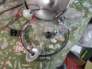
The wiring on the headlight case is replaced with a GBS loom, then everything is keyed and foolproof - theres only one way it can all go:


First time on the car, although it will come off again to have the main fitting threaded tube shortened appropriately. I didn't use the dish shaped washer under the light mounting - its too big, I used a standard washer then the locking washer instead:

Nearside appears to be working, just trying the leads directly on the battery I have side light, main and dip beam.

Boot cover

I bought some tarpaulin eyes on eBay as grommets over the seat belt mounts. My original intention was to clip them through the boot cover but there isn't room - instead I modified four of them which will sit tidily around the seat belt mounts and get glued onto the boot cover:

I think it turned out ok;
'boot cover' written on the retaining bar as a note to me not to forget the boot cover must be fitted before I rivet the bar in place:

The rear trim in place; not finalised until I have completely fitted all the boot cover dots:

I'm not intending to fit the Zero roof so the boot cover will sit slightly lower on the panels & I need to make sure it clears the rear wheel arches too.

I lost the light around the back of the car & really need to at least line up the wheel arches before completing this bit -  called it a day.

Note - during IVA the boot is tested 'as presented' so make sure its closed and poppers in place otherwise the studs on the chassis, rather than the smooth popper tops, will be checked for radiuses.

Tunnel cover panels

The final stint at fitting the tunnel cover vinyl, and panels in place in the car. 
Its a tight squeeze getting these back in place now the covering is on, so definitely worth leaving some gaps between panels when fitting them:

I still need to finally fix the gear lever gaiter in place - its sitting too low currently.

Starting to look tidy; also needs another go with the hoover to tidy up the carpets.

Wednesday 26 December 2012

Stainless door and floor trim

While the vinyl was drying I continued with the last remaining metalwork; the stainless trims at the sides and across the floor.

They need some adjustment, dremel + metal cutting disk was perfect for this:

Then finished with plastic edge trim and counter suck rivets (which I like even less the more I use them - they just dont pull tight) :

It makes the car look tidy though.

Pegs & Aux Panel

Raid the peg basket

I thought I might get the vinyl covering on in one go,  two goes down and its getting close. The contact adhesive seems to need a little help while it dries - but luckily this time of year I can raid the clothes pegs to hold everything in place.

Note for reference - the plastic pegs are too strong and actually mark the covering slightly I stuck to wooden ones after this stage

I cut the covering to shape after the first glue was in place - probably simpler this way, i.e. for the first glue I didn't need to particularly line anything up accurately, and this second go the vinyl cannot move while I cut the tabs/inlets/holes etc:

Aux Panel

Last up - I decided to assemble the aux panel.
Its very tight now due to the layers of covering, but with a little persuasion will still go together. Buttons in place except the hot water push/pull which will go in after IVA.

I might get away with the rotary fan speed adjuster (bottom left of this picture) , I think it will sit in the exempt area behind the steering wheel,  if it doesn't it will temporarily come out.

All ready for wiring up.

Monday 24 December 2012

Tunnel cover - vinyl

With all the interior panels finally cut & fitted, I started on the covering. I'm using the stock GBS vinyl covering, it has a cotton/foam backing to give a softer feel. Light ironing on the reverse first to get rid of the creases from packing then upholstery glue & copious clothes pegs to hold it in place.

I didn't see any grain/direction on the pattern, but lined all the panels up on the fabric the same way just in case:

Once that goes off I'll trim/glue the edges and cut out/glue all the holes & add in the handbrake & gear lever gaiters.

Heater water control

I decided on a low tech, push pull control for the water valve, I cant match the other buttons on the dashboard style so this option seemed the most discrete. CBS sell these with about 1.5m of cable, its then cut to size & the loop on the end to pull the valve:

Push for cold:

Pull for hot:

I'll have to create some sort of label for it to get through IVA, I also need to double check those radiuses  on that knob. Worst case I simply won't install the knob for IVA.

Tunnel cover & Aux Dash fitting

Front tunnel cover

Since I have the heater sitting at the front of the tunnel the front tunnel cover needed its front edge modifying appropriately. It tucks right under the heater and allows the loom up either side:


Aux Dashboard panel

The only changes required on the aux dash are to open up the existing holes to the right diameter for my buttons & add in a few more. Notwithstanding the simplicity of changes it still took me a good while to make he changes.

I used a cone drill bit to open them up - its much more controllable on thre aluminium internal panels than the stainless. I also have the heater on/off pull added bottom left, another row of buttons at the top & a discrete adjustment knob at the side.

Controls will be:
   Top row: Fog Lamp, ECU Map switch
   Second row: Heater fan, 12v socket, Horn
   Bottom row: Heater water on/off pull (drivers side - fan speed adjustment)

..and in situe; The heater push pull also has a cutout in the tunnel cover panel not visible here:

Thursday 20 December 2012

E.T. Inspired tent

To treat the woodworm the ceiling had to come down & unfortunately my early 70s house designers had used Asbestos insulation -

Que. professionals with E.T. style tent, vacuum leak prevention system, clean room trailer with 'clean' & 'dirty' doors and all appropriate regulation/certificates inspections and precautions to remove the ceiling:

At least I can get back in the garage now... trying to avoid a '13' plate on the car (superstitious)

Next up is Rentokil for the woodworm!

Sunday 16 December 2012

Empty

No progress on the car over the Xmas break; The garage needs some work so initially everything is cleared out ready to have the ceiling at the rear removed. Turns out its asbestos insulation board so I'm having to pay a small fortune to get some expert removal, on the flip side I can re-insulate the ceiling properly when it goes back together and improve the warmth of the room above.

...and an excuse for a few more shots of the car in daylight: