Sunday, 10 June 2012

High pressure fuel pump & swirl pot

Destination for the fuel lines; The bracket for the Swirl Pot & next to it the HP Pump:

The swirl pot is attached by 4x rivnut & bolts to be removable, it looks skewed compared to the chassis tube, its square with the panel though, the tube runs at an angle.
(Still not completely happy with that brake line... it might move before it gets fixed)


Trial and error with the fuel pump ties - one needed to be above the lip on the pump can so it cannot move up or down, I only worked this out after fitting it along with its main inlet hose - the hose was trying to push the pump upwards & would have easily pushed it right out with the vibration of running.

Note - hindsight - the pump needs to be fixed with metal clips or fuel proof ties - normal cable ties are not good enough.

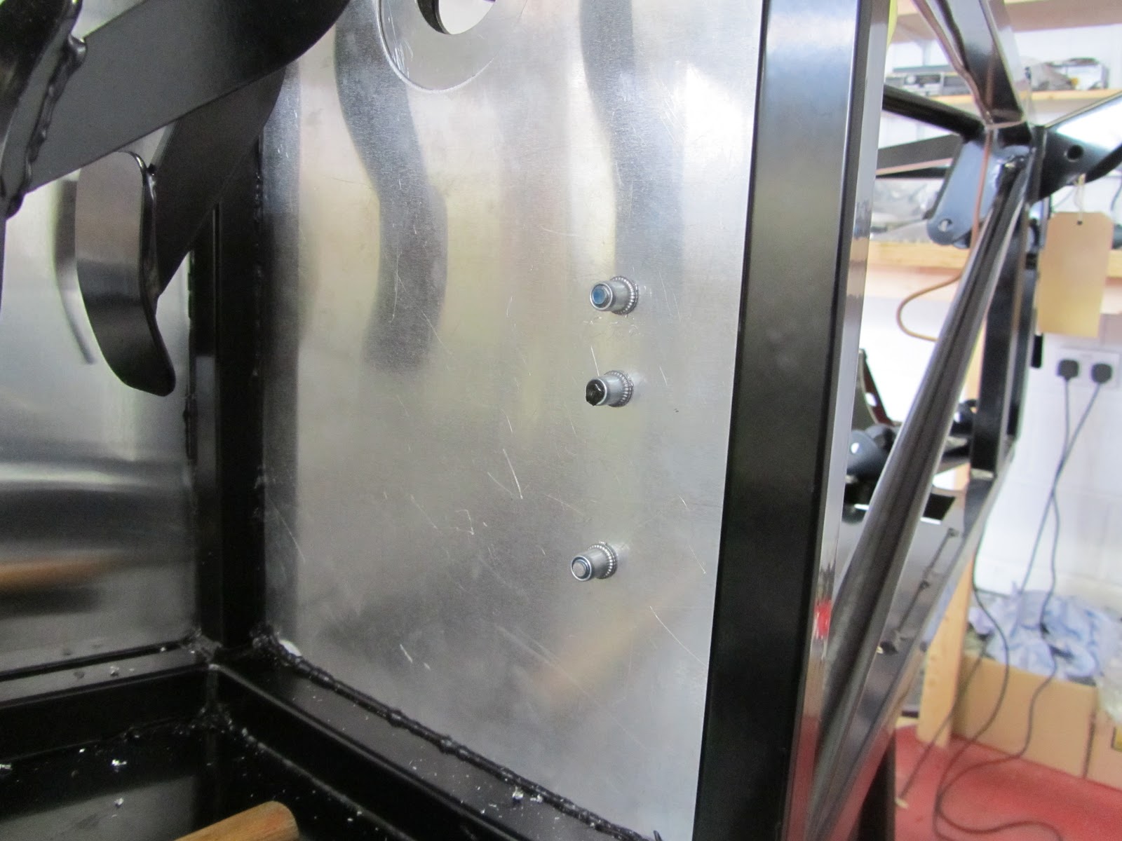
I needed to get this bracket on before the side panels to get to the rivets:
Not a great example of drilling here - opposite chassis member combined with bad technique let the drill wander.

Rivnuts holding the fuel pump; the middle one plugged with bond and unused once I realised one attachment needed to be above the fuel pump lip:

All ready now to connect the fuel lines from the LP pump at the back to the swirl pot.

Saturday, 9 June 2012

Low Pressure fuel pump

Rear fuel pump bracket, it comes pre-drilled with 4x holes - the one under the black filter needs opening up to 9mm for a rivnut, and then one on the right which is meant for the fuel pump - however I moved the pump a little to the right, its rear most mounting point also screws into the chassis & is not pre-drilled so must line up correctly.

Note - hindsight - the output side of the LP pump will leak unless PTFE tape is used for the brass insert.

(I swapped the filter jubilee clip round after this picture to make sure I have access when the bracket is installed)

Chassis rivnuts in place - 9mm holes required:
Closest and left hand one are dictated by the pre-drilled holes in the bracket.
Right hand furthest is located as the back rubber mount on the pump.

The fuel pump and filter installed:

From above, as per the instructions ensuring the jubilee clips are accessible from above through the boot floor access panel.

Wishbone bushes

Spent 2 hours fitting bushes and crush tubes:

  • Offside rear bushes x14 & crush tubes x7
  • Nearside front top bushes x4 & crush tubes x2, copper grease the thread
  • Nearside bottom, offside top & offside bottom to go.

My Process

  1. Clean powder coat from wishbone tubes with drum sanding kit
  2. Lightly grease the wishbone tube & bush
  3. Push the bush in place with G-clamp and vice
  4. Use calipers to find width of the bush pair
  5. Grind crush tube to this width
  6. Lightly grease the crush tube and push in with G-Clamp


Had enough of bushes - taking a break

Friday, 8 June 2012

Rear nearside wishbones

I made a start on the suspension;
Pushing in the bushes was fine, I cleaned up the powder coat on the wishbones first with the drum sander attachment then applied a little grease. The bushes are very tight; started them carefully with a G-clamp and appropriate wood blocks to stop damage, then wound them home with the vice.

Rang GBS to double check on washers and installation and was told:

  1. Crush tubes to be the same length as the bushes are wide to give a flush face
  2. Large penny washers against the chassis components with a smaller washer to spread the load from the bolt head/nut
  3. Fit penny washers as required between the wishbones and brackets to be snug and avoid bending the brackets when tightening
  4. On the hub carrier - fit washers either side against the wishbone bushes
  5. Aim for a 'snug' fit


It took me 2-3 fittings to get things right first trying with crush tubes as delivered - about 0.5-1mm longer than the bushings, then after realising it looked wrong and calling GBS for the above advice, purchased a bench grinder from B&Q and did it properly!

I'm much happier with it now, just need a replacement long bottom bolt which I managed to bend, and the top bolts which are too short.


(Top nut here will have a penny washer too when I get the longer bolts)

The holes for the shock needed the wishbone powder coat carefully removing, I used the side of a smaller (8mm in the 10mm hole) drill bit to clean it out taking care not to actually widen the hole.

I understand here, between the wishbone and hub carrier on the inside, its important to have a washer; cleaned off the powder coat on the hub carrier so it fitted nicely.

This is the supplied 90mm bolt, I've not tightened the nyloc, no point - it needs another 10mm to be long enough.

Must have tool in my opinion, and a bargain at B&Q:


Note;
I did try fitting this wishbone (before the advice from GBS) and in forcing washers in managed to bend (not sure if I bent it or not - anyhow - its bent and needs replacing) one of the long 240mm bolts which runs through the bottom of the hub carrier.

Note;
The top bolt through the hub carrier needs to be about 100mm + long, and neither of the supplied kit bolts are long enough.

Nothing torqued up yet, I have read elsewhere it needs to be sitting on its wheels before tightening the suspension bolts.

Thursday, 7 June 2012

Nearside tunnel panels & crescents

Passenger side tunnels just fitted and drilled, held in place with Clecos for now. The front footwell panel has to go in before the brake line is fixed to it, but probably after the gearbox is in and filled with oil.

I've still not completely decided on the order - so just fitted but not fixed for now.

Tunnel fitted & drilled; this panel just needed about 5mm nibbled off the top edge on both sides. These two panels will be fixed once the prop shaft is bolted to the diff.

I also have both inside crescent panels riveted and bonded in place:

Wednesday, 6 June 2012

Brake line routing complete

I've routed the lines; nothing fixed permanently yet for a few reasons:

  1. I'm not completely happy with the drivers side routing; I couldn't get through the top of the steering bracket but need to make sure I leave room for the swirl pot/high pressure fuel pump on the bulkhead
  2. I dont have the handbrake kit yet and want to make sure I don't attach the brake lines to foul the handbrake & lines
  3. Need to test out the supplied plastic P clips with a rivet - I have this feeling the rivet might crush/snap them (it doesn't tested them here - P-Clip rivet test )

Ready to be clipped - it will be tight to the tunnel rail - only moved here due to masking tape:

Not entirely sold on this route -
I covered any corners/potential rub points with clear plastic 'fish tank bubble' hose.


Rear end;

I almost started fixing these then realised; Firstly the passenger side tunnel panels need fixing first - which must wait for the gearbox/prop shaft & secondly at the back end the wishbones have to go in before the brake lines to allow the wishbone bolts to be inserted.

+ see later - I moved the rear 4way union to give more clearance over the handbrake lines Rear brake 4-way relocated

Monday, 4 June 2012

Brake line routing

Unrolling the brake lines was a mistake - it makes them very difficult to thread through the chassis - starting to make progress though. I have routed the rear line & nearside - temporary held with masking tape until I'm sure they are in the right place.

I had to re-bend these to make sure I'm tight enough inside the pedal box:

I'll re-check these before fixing for clearance with the firewall position which sits on top of the chassis cross member; They also need some tubing where they cross the chassis to prevent chafing - either some tube from the local fish shop - or measure out and see if I have any spare vinyl fuel hose:
(it would be nice not to have the lines cross like that - but they have to somewhere)  
I connected the rear brake line from the single outlet nearest the pushrod on the master cylinder and the 2x front lines from the two outlets next to each other farthest from the push rod.

Rear routing, through the tunnel - the union will be bolted to the single central hole:
With hindsight I think the line should go over the handbrake mounting brackets - it leaves more room between the lines & the handbrake cables.

Nearside routing:
I'm going across the chassis at the rear tube here no chance of the engine or anything in the engine bay moving and pinching it.

More tubing will be required on the corner here to prevent chafing:


Offsite yet to do - I can feel my thumbs now after all that pipe bending.


I'm going to buy an M6 nut/bolt to secure the rear 4way union to the existing hole - the small rivnut and bolt the union came with can find another job later on. (ultimately re-drilled the hole and mounted with the original rivnut: moved the brake 4-way)

Diff - success!

I took the spacers round to Dad's and he turned them down on his lathe, 15mm top, 14mm bottom. Thank you Dad! (See later posts - these spacers could also be sized on a bench grinder)

Re fitted the differential and everything went together easily this time, especially as I got my wife to help - the extra pair of hands on the jack or pushing in bolts making all the difference:
  bottom bolt first,
  tunnel bolts next,
  top bolt last -  then all torqued up and rock solid, its not going anywhere.


I've drilled through the stabilising mount with the diff in situe - but need a longer bolt & spacers to fit it.

Saturday, 2 June 2012

Differential - fitting - first try

Tried to install the diff,
A great heath robinson setup with builders steps & the trolley jack taking the weight while I juggled with the bolts.

The spacers are tight / too big - its just far to tight in the brackets, It seems to be partly the powder coat, and partly just needing the spacers sizing correctly.

Distance between the chassis brackets is 206mm, Diff width 175mm - so I'm going to turn the spacers down to 14-15mm each and have another go.

It didn't seem like the front bolts were lining up either, I'll open the holes up before I try again and hope I can get away with not having to remove it.


It doesn't feel like I made much progress. Frustrating.

Seemed like a good idea at the time

I decided to underbody seal the rear axle well before fitting any running gear - partly due to some pictures I had seen of rot (not a Zero) where the floor panels are welded on the chassis.


On the positive side; Undersealed the various chassis & panel parts which I will not be able to get to later

On the negative side; Needs another coat to give me solid black, looks rubbish on the Ali seat back panel (exterior side only) & now everything has a coating of 'never dry' 'always make you black instantly' wax which no doubt I will get covered with installing the diff & shafts.

Its not coming off now!
(Second coat makes it look much better)