Tuesday, 21 August 2012

Rear panel - remove and start trim fitting

Now the rear panel is drilled, I removed it to
  1. Drill the pilot holes for the rear wheel carrier (red paint markers in evidence)
  2. Clean up all the swarf around the holes
  3. Remove the shroud & fit/glue on the trim

Trial fitting of the first length & how I am intending to do the join between the two types - to be glued in place in due course

The carpets were trimmed down flush with the chassis tube, shroud ends cut to length (note the trim thickness adds 2-3mm to the shroud arm length required), trim measured up & the shroud marked at 10cm intervals ready for drilling:

I decided to cut the shroud arms rather than bend along the horizontal chassis tubes. I have seen the later done on other builds - trying something different.

Quite a slow job, but it looks pretty decent so pleased with the result so far.

Rear panel - finish fit

Finishing off the offside rear panel; the dowel is holding the roll bar diagonal in the correct position ensuring everything is level. I spent a lot of time ensuring those tabs on the corner did not overlap and butted edge to edge to give a smooth curve before locking in place with the rivet holes.


Rubber grommet & masking tape on the drill in an attempt to avoid scratching the external finishes when drilling the rivet holes:

Underside - taking care not to drill into the fuel tank, there are more rivets holes than clecos here 3x either side on each of the straight and diagonal chassis tubes (perhaps I should have fitted the rear panel before glueing it in place?) (+ must turn that nearside bottom suspension bolt around)

Finally the rear quarters where the panel locates on the side chassis rails:

The only remaining holes are for the spare wheel carrier - I marked their position from the inside with a dab of paint. I'm intending to drill the initial holes through from the inside - re mount the panel then open them up carefully with the dremel. (Again - this might have been a little easier if I hadn't fitted the fuel tank already)

Monday, 20 August 2012

Normandy

No progress for the last week or so, I was on holiday in Normandy for 10 days. It does mean I have the best part of this week off work to play with the car though!

There was very little sign of Seven's except what looked like a blue Caterham in Saint-Valery sur Somme on the way back, and only the odd Renault 4 van or 2CV in terms of other classics.

Assuming the Zero will clear the Eurotunnel carriage boarding ramps northern France is a stunning area to drive/tour; 80mph limits on motorways/dual carriageways & 60mph through the country roads with very little traffic even in the height of summer.

Completion parts order preparation

The only progress was starting to think about the final Kitspares orders for completion:
  • Seats
  • Seat runners - might go CBS duel side locking
  • Windscreen wiper kit
  • Stainless instrument surround
  • 'Zero' grille badge
  • Lambda blanking plug
  • Rear view Mirror - might go CBS
  • Wing mirrors
  • Boot cover
  • Gear & handbrake covers
  • Bonnet locating pins ? - or aero catches?
  • CAT
  • Silencer
  • Windscreen kit*
  • Diffuser*
* Required after IVA

Yellow = Ordered 31/8/12

Green = Received 15/9/12


Clutch release bearing

The replacement clutch release bearing has arrived from GBS - so all good to go modifying the gearbox bell housing and getting ready to install the engine.

Friday, 10 August 2012

Idle Air Control (IAC) Valve


Should I try and fit the IAC (Inlet Air Control) Valve?

Richard at GBS said I should keep it - but theres no place on the modified manifold or plenum to install it. Some how it needs a feed of external air in one side to bypass the throttle on the other. Its not particularly essential; just the difference between manually adjusting the intake butterfly stop & ECU control of air at idle via calibrated table lookup.


    My Design 1

    Something like this might do the trick to mount the IAC against the plenum and allow an inlet of atmosphere. It would need some sort of filter on the intake. The plenum would only need a single hole for the air coming in, and a couple of tapped holes for mounting the valve to this block and to the plenum.

    One hole straight through from valve to plenum, one coming out of the side for air intake. It could easily be square rather than mimicking the mounting bezel on the IAC itself.
    Asked GBS for a quote to build this

    My Design 2

    Simpler version focusing on the functionality required and considering the tools I have available:
    Bought some 50mm aluminium bar from Ebay to try this myself Only 10mm high, the biggest challenge will be the 16mm hole - perhaps a better job for Dad's lathe or a coping saw than any drill?

    Marked up ready for drilling & cutting: (I need a lend of Dad's drill press to drill these holes completely vertically)

    Mounting should only need 3 holes in the plenum, i.e. flush to a flat side & if I mount it near the intake I should be able to reach inside to push the bolts through & avoid having to tap them.

    Continued here: IACV Part 2

    GBS Design

    GBS are also producing a prototype design along different lines, fuel hoses to connect to the plenum outlet and mount the IAC separately; i.e. cut the hose, the IACV on the bracket, one end of the hose to the plenum outlet and the other to an air filter.


    Still in two minds whether to use the GBS bracket or my own..

    Monday, 6 August 2012

    Rear panel - level ?

    Only a quick check this evening - a little issue assessment: 
        How far off is the rear panel?
        I talking re-drill/fit the entire the shroud -or- can I correct it as I finish the offside.

    Issue

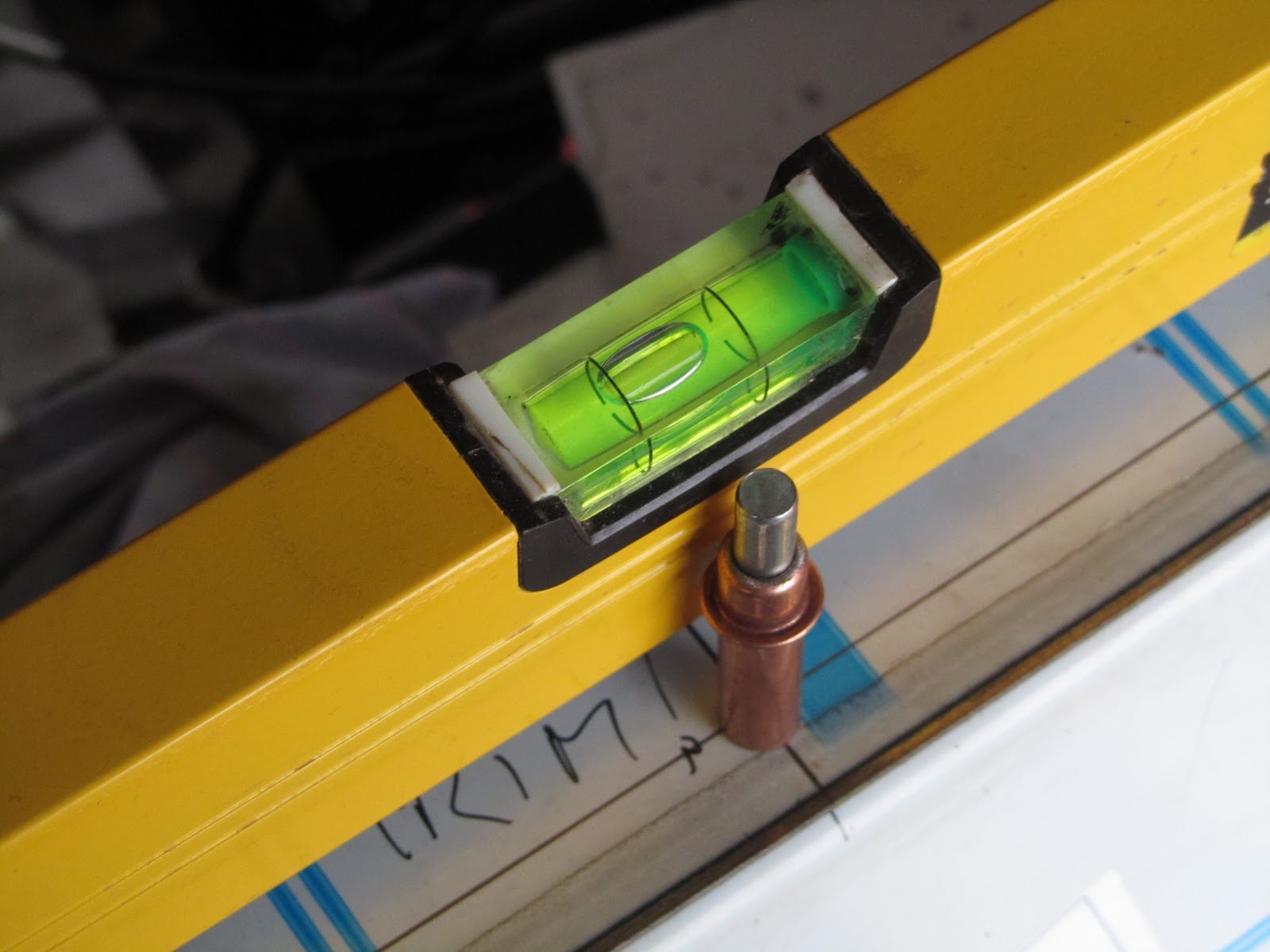
    Reference is the chassis rail which runs along behind the seats, its sitting perfectly level:

    Compared with the back edge of the rear panel - the offside is low. This is with the rear edge and nearside all drilled and cleco'd:
    ('Trim' written on the panel is a note to me to make sure I put the edge trim in place before starting to rivet anything)

    Correction

    A good pull about 1cm back on the offside roll tube brace can bring it into line, which means I should be ok, provided I get it lined up before drilling and fully fitting the offside.  I think I just need a brace to prop it into the right place... 

    It seems to be ok!  at least no re-work required, I just need to be in the right mood to line up, drill and cleco the offside :)

    Sunday, 5 August 2012

    Rear panel - top edge fit

    I began working the top edge. Marked out a line 1.5cm in from the edge all round then 10cm spacing starting in the centre and working outwards.

    I did try marking the sides 10cm spacing at first, then measuring the tab distances; I ended up simply visually looking at the position of every other tab when I had the panel where I wanted it and marking/drilling each one individually, working towards the front of the car.

    That first hole around the corner, I drilled through the top shroud, then lent on the panel to get it in the right place and marked through the hole position to the tab underneath. Drilled the tab separately then put in the cleco to hold it.

    Once the first one was in, the g-clamp held the straight side & I could drill through shroud & tabs all the way along.

    My test piece of trim visible on the left of this picture; I probably need one more rivet right on the corner..

    Level?

    The trailing edge of the boot is not quite level - maybe 1-2cm 5-10mm higher on the nearside when compared with the top chassis member which runs behind the seats. Its only noticeable if you look at the car square on from front or back with eye level at boot rim level - but now I've seen it I'll have to at least try and do something about it. I need to remember to adjust the diagonal roll bar braces before fitting the offside - once the holes are drilled & clecos in place they become rock solid.

    I did actually read about this on Shaft's blog months back - of course, didn't remember to check my own before starting the panel - doh!

    The Olympics seems to have brought out the summer weather, there was heavy rain this morning but its left behind bright, really hot, weather. To hot to mess about in the garage all day!

    Saturday, 4 August 2012

    Rear panel - trial fit

    Tom-Zero on RHOCaR was after some info on Wheel stud length, just the excuse I needed to get back in the garage: the car up on axle stands, remove the rear wheels and trial fit the rear panel.

    All seems fine, the sides plainly need some more work to straighten them but that will come when they are riveted to the floor & chassis (note the trolley jack is not holding the car up - all the weight is on the 2x axle stands)

    The top curves don't look bad, the front edge lining up nicely with the base of the roll bar and the diagonal chassis member it will be riveted to


    Floor...

    Spot my deliberate mistake - suspension arms - one side is bolt head to the front, the other side is nut to the front :| . Somehow I need to mark where the spare carrier will attach and dremel out a couple of holes & think about the spare wheel centre mount.


    Floor fit & space to fit lights

    The floor filler panels are nowhere near the sides yet. Notwithstanding a lot of work to finish the fit, the carpets all meet at the corners, I'm thinking perhaps a canvas liner - under the carpets - might be a good idea to make sure there are no holes in the boot - otherwise I can just see the contents working its way out onto the road through all the smaller gaps.

    This shows the space between fuel tank and the panel - I need to check how the fog/reversing lamps are attached before any of this is permanent.

    The next job is start drilling/cleco'ing the mountings for the panel. Aidan's blog shows shaping the curve by progressively drilling and attaching to the top shroud, working from the centre - I might try that.

    Rear panel - tabs & bending

    Planning

    Time to have a go at fitting the rear panel, first off I thought I would work on the ground, the back/floor bend is already put in at the factory.


    Looked at it for a while, changed my mind about the floor, tidied the bench, and moved everything to working height. I marked a centre line on the top & bottom edge of the panel, and centre of the shroud panel which should help lining things up a little later on.

    First try: Guides and thumbs

    Ultimately decided the first part to bend should be the tabs on the bottom edge, this is out of sight once built and I thought it would be a good area to practice on. My first attempt was to clamp scrap wood either side of the fold line and push the tabs up with my thumbs. The result was a straight line, but not a very tight corner.


    Advice & Better technique: Mole grips

    I gave Richard @ GBS a call and asked for some advice, a few points I really wanted to clarify:
    1. Should I bend the top edge tabs before or after curving the panel? -> tabs first, bend afterwards
    2. How to bend the rear panel -> push into the corner of the bend while folding
    3. How to get tight bends -> mole grips!
    I tried out mole grips on the other bottom edge, there wasn't room for a straightedge, but the mole grips give a much tighter bend. I used a couple of strips of steel on the wider tabs to effectively widen the jaws of my grips. I checked an offcut of trim against my folds to double check I was getting a good enough result, i.e. to ensure the folds are tight enough to be hidden by the trim when I come to do the top edge.

    The technique appears to be pressure towards the bend point at the same time as making the bend.

    Not a bad job, just care on each tab to get the nose of the grips a little back from the fold point. The burned plastic is residue from laser cut when the panel is manufactured - it will be peeled off once everything is installed.


    Bending the ends

    Next up is bending the ends inwards to form side panels. I have the GT/Wide chassis so these only go as far as the high point on the wheel arches. I tried a technique I have seen on other builds, using the rear shroud panel inside the rear panel as a former for the curve. It wasn't working for me so I removed it.

    Slowly bending each side up, I found a rolled up old towel useful for putting pressure inside the corner as I was bending, it seemed to help avoid creasing the metal due to too much localised pressure. The floor panel (vertical at the back in this picture) also needed bending inwards a little more - there is a locating hole on the top tab, and the sides to line everything up.

    Note - The bottom two holes on the sides are to mount the diffuser, the small hole in the last tab of the floor lines up with the single smaller hole on the side panel.


    I think the next step is to offer it up to the rear of the car - which I suspect will be easier if I raise the chassis on axle stands and take of the rear wheels. I'm also going to check some other blogs re position of rivets.

    I have never done anything like this before so pretty happy at how it came out!

    Engine mount brackets prep

    The engine mount rubbers need the lugs removing, these look like rubber but actually have steel plates inside (I found out the hard way) so I used the angle ginder to take them back flush with each face:

    Checking the rubber mounts against the chassis brackets the threaded rod was just protruding, I decided to cut off 2-3 mm so it could be tightened without hitting the chassis beneath, before & after pictures:

    All ready to go:
     

    I was intending to bolt these onto the engine, but I have to wait anyway (see clutch bearing issue) & it might be better to bolt on the brackets after the engine is lowered into the chassis.

    Friday, 3 August 2012

    Raceline Sump install

    I already prepared & assembled the sump kit here: Raceline sump preparation

    The engine is new and has the original unused oil which needs draining: I may well put this back in later and use for running in Actually ended up changing the oil for 100% fresh:

    18 bolts to remove the lower pressed steel sump, it took a little levering off to break the seal & its very easy to miss a bolt!

    This reveals the pickup pipe which is removed, 1x bolt & 2x torx bolts:

    Removing the pickup pipe allows unbolting the main sump, I re-used the engine tray so it didn't drop to far:

    Then install the new Raceline sump. Before offering the new sump up I made sure the old sealant was completely removed - there is a blob in each corner on the block where the end plates are bolted on.

    A bead of loctite 5922 gasket material outside the rubber seal, especially at the corners to ensure a good seal then lowered the block carefully onto the sump, checked the flywheel end of the block was lined up and gradually tightened all the bolts. Centre first working towards ends tightening a little at a time:

    All the bolts are eventually torqued up to 18 lb/ft as per Raceline instructions. Its really difficult to get a torque wrench in, but feels like the larger risk is over torquing and stripping threads than under torquing. I had lowered the engine onto my toolbox just enough to stop it spinning around as everything was tightened:


    My heath robinson gripper to remove the large oil filter made from the lifting strap & mole grips. I didn't quite resort to the screwdriver through the case technique, but did manage to dent the old filter in the process. This is replaced with a shorter profile filter (no picture)

    Back down on the deck to let the gasket sealant cure a little overnight then I'll put the (Fresh New) oil back in:

    The install went exactly as described in the Raceline instructions, the only hairy part is having the engine dangling on the end of the engine hoist; and the acid test yet to come when the liquids go back in & I find out if I have any leaks.

    The engine has to wait now for a replacement clutch release bearing from GBS. Then I can attach the gearbox and think about installing it in the chassis.

    Breakage

    My engine dollie which I managed to kneel on and snap the chipboard - I might rebuild it.

    The oil pan I bought,  leaked from the smaller cap - I tightened it to stop the leak - and it split the cap completely. Pah - hate plastic!