Sunday, 9 September 2012

Plenum - install

Air Sensor

Final jobs on the plenum to install - first the air temp sensor, I used a little instant gasket to make sure it has a good seal:

Gasket

I cut out a gasket for the plenum, I'm not really sure if this is necessary or not - the plenum mounts on the remains of the OEM air intake which is plastic, so some sort of union between the two would seem like a good idea (also saw Simon Bradley used one on his blog). Removed and cleaned up the intake hole cut outs after this picture:
Note; My installation suffered from air leaks once running; this gasket was re-visited and re-installed with instant gasket either side to ensure an air tight seal against the plastic adaptor.


Ready to install

All set:

I checked the length of the GBS supplied bolts which replace the OEM ones by winding into the blind holes (see general paranoia about winding things in too far and damaging the casting); all good - simply bolts on to the plastic adaptor which holds the fuel rail and injectors. The fuel rail had to come off to allow access to all the plenum mounting bolts. The IACV is sitting in just the right place to let its plug & loom miss the two chassis rails:

Reinstalled the fuel rail

With hindsight, its a good idea to get some of the engine loom in place - especially the injector loom before putting the fuel rail back on. Its not impossible with everything in place, just more tricky.

Close up of the 'busy' end of the fuel rail - my modified fuel inlet pipe, the plenum vacuum pipe & the engine loom socket all in close proximity, just out of shot is the cam cover breather pipe too. There's quite a dint in that fuel line pipe where I bent it into a different direction - I'm hoping its ok - I'm also hedging my bets by obtaining another fuel rail pipe as a backup incase I decide to re-work this area.

Saturday, 8 September 2012

Intake & Plenum prep

Clearance

Next up is the plenum, High Pressure fuel lines to the fuel rail & intake side loom. There is no clear part to go first so I spent some time checking clearances & positions of various items before anything is fixed:

Bonnet on to check head/side room, on the GT chassis there is plenty of room all around the intake side, the bonnet virtually sits flat on the top of the timing belt cover at the front of the engine though:

HP Fuel line layout

Space established, I need to decide on the lines from the swirl tank to the fuel rail. I have already decided (I think) to feed the OEM fuel pressure regulator at the front of the engine, and take the return from the rail at the rear via the cut down fuel rail tube.

Three options present themselves for routing the lines:

A. Take the line along the chassis tube and a gentle arc around the outside of the plenum: <- This
     I like this option - looks neat, no tight turns and leaves the other side of the plenum for wiring
B. Still take the line along the chassis tube, but inside the plenum line up to the regulator:
     Experience on RHOCar shows this option has been done before & known to be ok

C. Take the line across the top of the fuel rail and loop back to the regulator: <- Not this
     Unlikely option - the loop just looks messy 


The decision (between option A. & B.) will be based on any consensus from RHOCar & I may also ring GBS to check.

There seems to also be an issue with clutch cable routing - very tight under the plenum, will need checking before it is attached permanently.

Plenum prep

Before fitting I can do a couple of jobs on the plenum itself, fit my IAC Valve & fit the butterfly valve assembly. The IACV needs 3 holes, and needed to be in a location where I can get to the nuts on the back for assembly. I checked the location to make sure it would also miss the chassis tubes when installed.


Inside, lock nuts so should be little chance of losing them into the engine, and the second picture shows a glimpse of the trumpets on each intake:

Almost ready for fitting (needs the air temp sensor fitting too):

Update - later I opened up the main IACV air inlet hole on the plenum to be larger than pictured here and closer to the actual valve size, i.e. 16mm which lets the IACV have more control over the volume of air let in.

Friday, 7 September 2012

Alternator & Steering column

Alternator

Alternator mounted, I used a straightedge to line up the front pulley face with the crankshaft pulley - I'll double check when the engine actually turns over that its all aligned. It was easiest to take off the plenum & intake manifold adaptor to get at the alternator bolts:

Belt in place - possibly a little slack for now:
The star on the crank end bolt & the masking tape on the chassis rail were markers to align the engine.

Update - I should have cleaned off a little of the powder coat on the mounting brackets to ensure a good earth for the alternator. Remediated later with another earth line on the intake side of the engine.


Steering column

The steering column came out to drill the engine mounts - so now back in with the correct steering rack bolt which locks the column in place; it can't pull off the rack spline even if the nut came loose. Centred the rack beforehand.

Fuel rail re-work


I didn't like the fuel rail as it was, I also had some specific space issues at the rear end. This area has an engine loom plug, the plenum vacuum outlet and the end of the fuel rail - its really not practical to have the fuel pressure regulator here too:

I moved the OEM fuel pressure regulator to the front of the engine:

Then modified the original return pipe, shortened it and left enough to attach the high pressure fuel line to:

This is the result - I hope its a neater arrangement:

The plenum is only temporarily in place to align everything & let me see how much space there is.

Wednesday, 5 September 2012

Starter bolt chassis clearance & engine mounts

The lower bolt housing is very tight to the chassis, best advice was to file it back a little: Propped the engine on a block of wood to give room to work & used the Dremel sanding drum & a hand file:

Resulting position with the engine lowered:

Engine mounts

This allowed me to complete the engine mounts, bolting to the chassis:
4mm pilot holes followed by 8mm for the bolts.

Offside there is a problem - the top right bolt is so tight to the chassis rail I can't get the nut on underneath.. I need to think through some options:
    Re drill the bracket rotated a little clockwise <- This + shaped the nut to fit against the chassis
    -or- Use a spacer tube underneath with a longer bolt
    -or- Run with 3 bolts on the offside

Nearside is fine:

Tuesday, 4 September 2012

Tidy up - Engine mount & Fuel line run

Engine mount

The nearside mount was tightened up against both the tube standoffs & the projection from the block casting. I wasn't keen on this - the casting wasnt completely square behind the bracket & I wanted a washer between the standoff tubes and the casting too. I re-worked inserting washers so all the stress is taken through the bolts & standoffs & nothing touches the casting projection:

The gap I wanted between the bracket and casting is visible in this shot:

Fuel line run

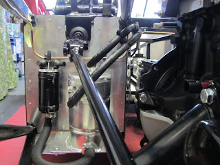
With the engine in place my original fuel line positioning was too low & close to the bell housing. I decided to re-route slightly higher which nicely misses the bell housing. I also flipped round most of the jubilee clips to be accessible from the top of the engine bay:

I'm thinking about another tie wrap on the left hand side as a backup:

Well clear of the engine/gearbox now:

Sunday, 2 September 2012

Tight

This morning I lined up the engine on the car centre line and checked clearances.

The starter motor bottom bolt is (I think) a little too close to the chassis, its about a 3mm gap. I'm going to gather opinion, RHOCar & GBS before I change anything, but suspect it needs cutting down a little.


The bell housing cut looks fine though, a good 10mm clearance from any panel/chassis tube. With hindsight the top cut could have been straight (aesthetically) but not an issue from a clearance point of view.

Answer-> Consensus so far seems to be its probably ok, however GBS is recommending taking a little off to avoid it potentially catching under hard acceleration.

It will be easier to do now than later, I can prop up the engine a little to get access with the Dremel without having to remove & re-install it.

Saturday, 1 September 2012

Engine install

Next up - installing the engine assembly. 

A milestone job & relatively involved one having the engine swinging around for much of the operation. It would possible as a one man job, but much easier with two - my wife helped - then you have a point man to look out for clearances etc, and when lowering in the engine one on the hoist & one one guiding the gearbox mounting into place.

Oil pressure sender & underside bolts

A couple of minor installs, the oil pressure sender (on the left of the OEM ford one) & as the engine was raised up I could get access to the starter motor bottom bolt & 2x bell housing bolts. The bottom starter bolt seemed to bind part way in so the washers let it do its job without breaking something.

All ready to go

The load balancer was good at changing the angle of the assembly, I shortened the back chain to give a general downward angle. Because the chains were attached at diagonal opposite corners it did mean the engine would twist as the balancer changed its angle but the effect was minimal & could be offset with a little man handling:

Chassis first time out in the open:


First attempt

The legs on the engine hoist were the biggest liability - they are too tall to run under the Zero's front suspension which means the car needs raising. When raised on axle stands they seem to want to be in exactly the same position as the hoist legs: tried the axle stands inboard first:

Then axle stands wider under the lower wishbones & lengthened the hoist jib to maximum reach:

Rethink & Success

Finally I found the best axle stand position was just one in the middle.
We slowly edged the engine assembly back/down & adjusting the angle as we went:

The final stage I had a couple of bits of scrap under the back of the gearbox casing to guide it back at the right height into its mount. The gearbox slots into its rubber mount at the back, then 2x arms are bolted to the engine sides and sit on the 'card' powder coat protectors:

Engine in place

At this stage I have only bolted the engine mounts to the engine & not to the chassis, I need to check a couple of points where clearances are a little tight & make sure everything is aligned centrally down the car. The fuel lines on the offside currently touch the bell housing & the bottom bolt on the starter is very close to a chassis rail on the nearside:


The padding will come off as soon as everything is fixed in place, its just there to protect the powder-coat finish on the chassis rails underneath.

I still need to check the clearances & drill/fix the engine mountings to the chassis; but its essentially in!