Friday, 30 November 2012

Heater

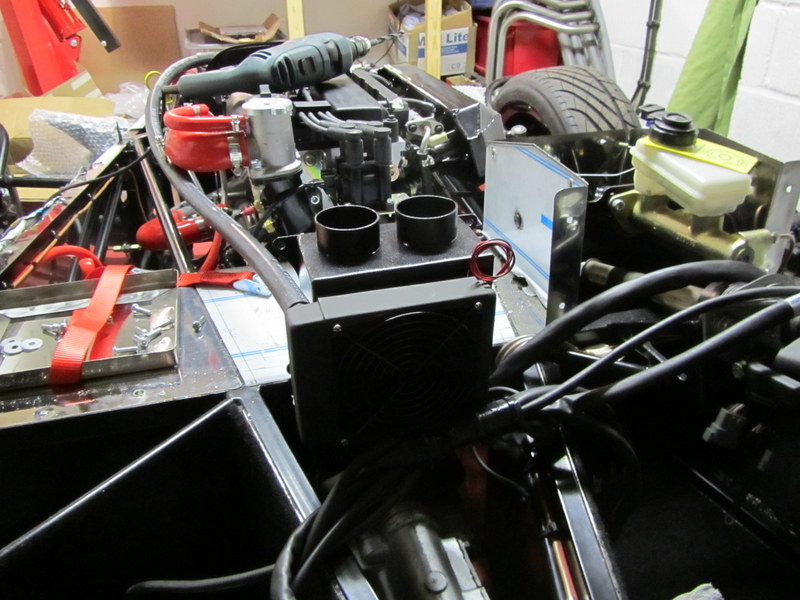
The scuttle is on, hopefully for the last time now;

Heater in first, with the water inlet hose through the firewall:

With hindsight (search the blog for heater) I would have done things slightly differently, the vertical mount on the heater outlets is fine, however I think:

  1. I would have taken the bottom return through the bulkhead rather than under it -or- mounted the heater about 2cm lower
  2. I would have left the back-plate where the heater is mounted in its vertical orientation - holes top/bottom rather than left right.

Thursday, 29 November 2012

ECU Mounting bracket

My final decision on the fusebox / ECU position; The heater is going to be where a stock Zero fusebox goes, the Fusebox will be next to the wiper motor & the ECU sit in front of the wiper motor on a custom bracket:

1x envelope sketch & 2x cereal packets later I have a template I am happy with, most of the re-work spent simplifying it and making a decision over mounting to the scuttle or the chassis. This bracket will mount to the chassis and the scuttle drop down over the top:

I used 3x metal cutting disks on the dremel to cut this out of 1.2mm stainless. I have no metal bender but all things considered it came out pretty much as planned:


The wood is to mark 100mm in front of the firewall to make sure I don't use the space for the wiper motor:

Drilled; 2x rivets into the side chassis tube & the tab on the diagonal chassis tube will be bonded in place (possibly riveted too once the bond is dry). The holes along the bottom allow access to the ECU programming plugs and status light:

Mocked up just before fixing to double check positioning & make sure I still have access to scuttle/windscreen mounting holes. I'll play the stability by ear, if it wobbles too much I can run a stay back to the firewall easily enough:

I was mulling over a false firewall inside the scuttle to mount the heater & fusebox; that might be overkill though...

Sunday, 25 November 2012

Instruments

The dashboard inner panel has a small cutout to allow the end gauge to fit; It needed a little adjustment (marked here with black pen) with my instrument positioning:

Then the dash comes off & a 3" strip of vinyl/leatherette to cover the gap between it and the scuttle panel. Bonded in place with contact adhesive, once it goes off the inside part will be cut back & the edge which shows covered with some 'U' trim:

Harness

A little quiet time to work out the dashboard harness. I'm using the GBS 'plug & play' loom which generally is labelled up really well - except for the dashboard.. Not too hard to work out - each plug has a standard black, green & red white stripe:
    GND - Black
    12v - Green
    Illumination - Red/White stripe
      (didn't need to test these 3 - so don't rely on my info - 
         Smiths seems to use opposite colours to GBS for 12v/GND)

Then signal on the remaining lead (double checked with a tester back to the dash plug):
    Volts - no extra line, just has the green, black & red/white
    Fuel - Yellow
    Water - Blue
    Oil - Orange

The stock loom then dictates the instrument layout. From the front, left to right - Volts, Fuel, Water, Oil, Speed, Revs:

Note - during IVA the stainless surround was checked, only the left most dial area was outside the exempt steering wheel zone, but the edges had to be blunted; i.e. filed smooth. My tester wasn't keen on the slightly rough edges on the rev counter end - but couldn't do anything about that because its behind the steering wheel.

Saturday, 24 November 2012

Dashboard

On with parts that can only go in one place; Dashboard fitting, this will also further define how much room I have to play with inside the scuttle area.

I started with the middle bolt hole, working out its location with measuring and dead rekoning, then the same with the end bolts at either side. My thinking was once these 3 are in place the scuttle can come off and its shape cannot change while I 'find' the other hole locations:

On the bench, the ratchet strap is to make doubly sure the panel stays the correct width.

I drilled pilot holes from behind through the rivnuts then opened up to 6mm for the bolts. There is a margin for error i.e. the bolt heads will cover minor adjustments in the holes. I only had one of the nine bolts cause a problem - the top left hand corner hole was waaay off and shows a little from under the bolt head:

While the scuttle is off I might as well drill & fix the instruments, I used the stainless surround as a template, with speedo & revs central over the steering column and using the bottom edge of the dash as a datum/straight line for lining up everything else:

No picture of the intermediate stage; lots of dremel work with the router bit & drum sander attachment, subsequently filling the workbench & much of the garage with red dust (again). The drum sander is perfect for taking the GRP back until the gauges fit.

One of the most fiddly steps was removing the protective plastic from the stainless surround, white spirit helps get any glue residue off then wax polish to remove most of the fingerprints. Its not perfect, but looks pretty good :).  I've gone for Smiths flight gauges, the standard GBS option, which has warning lights built into the rev counter meaning a clean, minimalist dashboard:

Ready for dismantling & the return edge on the scuttle covering with vinyl & edging, then its back to fitting all the equipment inside!

ECU & Fuse box position

Trying to work out how to fit the fusebox, ECU & heater under the scuttle. The cardboard cutout is a mockup of the fusebox.

I think the best options so far are:

1. Fusebox on top of ECU: (3 dimensional thinking)

2. ECU at right angles:

3. (not pictured) , ECU as per option 1, Fusebox next to the lower button panel

I've been thinking about all sorts of combinations - still not completely decided. The ECU bottom edge must face down to provide access to the connectors, the fusebox might go on the other side of the heater which would be even better - out of the way of the heater hoses.

There is room for the ECU on the driver's side, but might be limited by the loom....

Still not completely decided - I'll add some more fixed parts and hopefully it will all become clear.

Friday, 23 November 2012

Heater position

With the wiper motor position known, next is the heater. I'm decided on a vertical orientation to:
  1. Keep the water pipes on the nearside, where the engine cooling circuit is
  2. Avoid them being level and getting an airlock at the top of the heater
  3. Line up the top pipe sligtly lower than the engine water rail, to hopefully let any air locks naturally out of the heater.
The air intake will take air from the cockpit, inside the car. I can't see the need for an airbox under the bonnet with an open top car.
   although...
If the heater radiator was on the engine side the plumbing would be easier - but it would need an air intake from somewhere....


Just enough room to take the top hoses either side - they will come out just under the dash. The bottom hoses will be above the gearbox and come out of the transmission tunnel just about where the passenger knees/shins are:


This is the heater position on the chassis - i.e. when bolted to the scuttle and the scuttle lowered in position. Showing the location of the hot water feed pipe which will have a take-off from the red silicone elbow near the thermostat:


Next up - working out the location for the fusebox & ECU - not much room left in the scuttle space.

Windscreen wiper motor & gearboxes

Even though the windscreen will not be fitted for IVA I need to work out the layout under the scuttle, so I'm going to fit the wiper mechanism then remove:

Getting ok with pipe flaring now then a couple of dowels help bending the last pipe: 

Not a bad job... except... spot the deliberate mistake!  I forgot to put the nut on the pipe before flaring the ends, I didn't even notice until I had bent the pipe into the right shape. I knew it was going too well:

Luckily I had just enough length to cut off the flare, put on the nut and re-flare:

In situe with the wiper motor just offered up for position at this stage. I also have a couple of marker holes just above the motor through the firewall which need opening up for the battery cables - they are waiting for a cone drill:

The string was my tape measure for working out how long to cut the end bent tube & the large rubber pad is in the wrong place in this picture - it should be between the motor and the firewall.

I have the gearboxes the other way up from all build diaries I have seen; Once I can get some power to the motor I can work out which way it moves and flip over the park position cam if I need to. The gearboxes seem to take up less room this way around.

There is a final tube to go on the end - I'm not sure how long to make it though so it will have to wait until I've actually run the wiper motor & checked the maximum extension of the push rod/spring.

Wednesday, 21 November 2012

Battery tray

Next big job is fitting out the inside of the scuttle, wiper motor, fusebox, ECU etc. In preparation the battery position is required so I can work out where the cables will pass back through the firewall & make sure I don't mount the wiper motor in the way.

I positioned the battery first to check bonnet clearance then marked up the corresponding tray position squared with the front edge of the footwell.

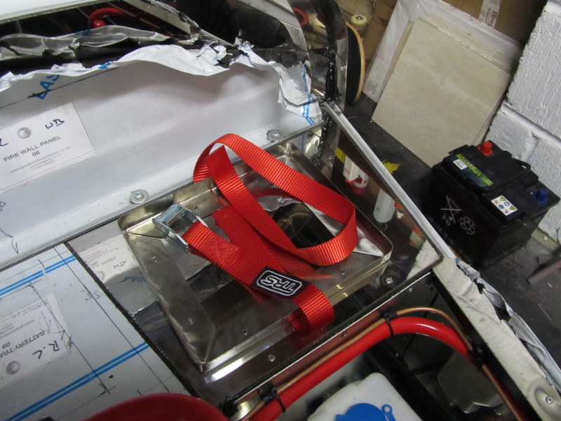
Straightforward job to fit onto the passenger side footwell with countersunk rivets; not forgetting the retaining strap which is pinched permanently underneath:

Notwithstanding this picture angle, the tray is dead square, all corners lined up and checked before riveting.

Sunday, 18 November 2012

Red!

Dashboard up next;

There are 9x rivnuts to fix around the dashboard panel, with hindsight I should have fitted them before assembling the scuttle; however its not too bad putting them in now:

The dashboard fit is dependent on the scuttle & the steering column cowl, so next up was trimming down the stock Sierra cowl so it fits around the chassis tubes & still allows the column to adjust:

First step was a little wax polish on the dashboard to give some protection.

I'm going for factory layout on the dials with a stainless surround. The surround position dictated by the cutout on the scuttle panel, then I used the same curve to start taking out the section for the steering column at the bottom of the dash:

3-4 goes each time checking clearance; The large chunks of dash removed with the Dremel router bit, and then smoothing & working up to the required edge with a drum sander attachment. 15k rpm seems to work best, eye and breathing protection a must!

Pretty good:


The steering column cowl is just temporarily in place to locate the dash, it will come off in due course to finish the column wiring: 

Nose in the background - I need to get under the car for its final fixing bolts:


Its too cold today to do much more, the next step is to drill the dashboard mounting holes & instrument holes. I think I'll need some sort of paper template to work out where the mounting holes are.

Saturday, 17 November 2012

Tidy up

A little tidy-up today:

  1. Double checked where the bonnet comes on the scuttle by temporarily fitting the nose & bonnet.
  2. Riveted the front edge of the scuttle top where it won't be seen under the bonnet, cut the tabs off & filed down any rough edges.
  3. Scuttle removed & a line of bond put around the edges I hadn't already covered, then put back on the chassis to make sure it dries in the right shape.
  4. I drilled a couple of the mounting holes in the nose where it attaches to the chassis top rails, deciding to use M6 nuts/nylocs & washers
  5. Flared the brake line I broke previously and fitted - I'm not completely happy with it though so might re-work before filling with brake fluid

Really I want to leave it all alone to let the bond on the scuttle completely cure - I'm not sure what to do next:

Decide if the fusebox is going inside or outside the scuttle then back to some wiring?

Perhaps start the dashboard?

Fill the brake fluid?